Electrical wiring parts and materials. Wiring gfci receptacles with a protected outlet.

To Gfci Outlet Wiring Diagram Moreover Switched Gfci Outlet Wiring
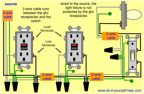
The source hot wire is spliced with one of the switch wires and the other switch wire is connected to the hot line terminal on the device.

Wiring diagram gfci outlet.
Wiring diagram for a switched gfci combo outlet.
Wiring diagrams switch light and outlet archives eugrab save.
This gfci wiring provides protection to a duplex receptacle outlet at the end of the series.
Dont use a gfci as a receptacle for a refrigerator freezer or other appliance as it could trip without your knowledge.
Gfci outlet with switch wiring diagram gallery.
The line terminals of a gfci outlet connect to the power supply conductors that are connect at the circuit breaker or fuse box.
Line essentially means supply.
In the event of a ground fault a gfci will trip and quickly stop the flow of electricity to prevent serious injury.
Electrical parts and materials for gfci outlet wiring projects should be approved for the specific project and compliant with local and national electrical codes.
A gfci ground fault circuit interrupter is a special type of outlet that detects dangerous ground faults and immediately turns off the power to stop shocks.
Wiring diagram gfci outlet refrence wiring diagram for gfci and.
This section covers do it yourself wiring of an gfci electrical outlet.
The source neutral is connected the line neutral terminal.
Gfci outlet wiring diagram.
Refer to the attached gfci outlet wiring diagram above for clarity or contact our in office electrician in mesa az free of charge.
What gfci outlets do is reduce the danger of deadly shock from faulty plug in cords and devices.
Gfci outlet with switch wiring diagram collections of used dimmer switch outlet bo electrical outlet symbol 2018.
So gfci designed as checking the difference between the current leaving and returning through current transformer of the gfci to protect device exceeds 5ma.
Take a picture of the wiring on the current outlet before disconnecting the wires in case you need to refer to it later.
Gfci wiring method article shows outlet wiring a gfi using the tailed method.
In this diagram the switch built into the combo device is wired to control the gfci outlet itself.
A gfci outlet is different from conventional outlets.
By connecting the load terminals on the last gfci the wall outlet at the end is protected and can be used just as if it were one of the gfci receptacles.
In the gfci mainly two wires connect as also shown in a diagram the current flowing from the source and coming back are some due to current laws.
You can replace almost any electrical outlet with a gfci outlet.
Gfci outlet wiring method this article and the electrical wiring diagram will show you how to install a gfi using the feed through method which will protect more than one outlet.
Electrical codes and inspections.
Identify the gfci outlet circuit turn it off and tag it with a note before working with the wiring.
50 Amp Gfci Breaker Wire Diagram Wiring Diagram Library
Help Needed With Knob And Tube Fed Light Doityourself Com
Find Where The Hot Or Neutral Is Open

Cooper Gfci Wiring Diagram Wiring Diagram Data Schema
Ground Fault Receptacle Wiring Diagram All Wiring Diagram

Wiring Multiple Outlets In One Box Online Wiring Diagram

Wiring Diagram Levitonb12 07899 0rw White Smartlockpro Gfci

Electrical Wiring Line Load Basic Electronics Wiring Diagram

Gfci Ground Fault Circuit Interrupter Types Working Applications

Wiring Double Outlet Box Wiring Diagram Data Schema
Single Gfci Wiring Diagram For Dummies Wiring Diagram Data Schema

3 Phase Gfci Wiring Diagram Wiring Diagram Database

Electrical Gfci Outlet Wiring Diagram Electrical Wiring In 2019

How To Reset Your Gfci Outlets And Circuit Breakers Laudan

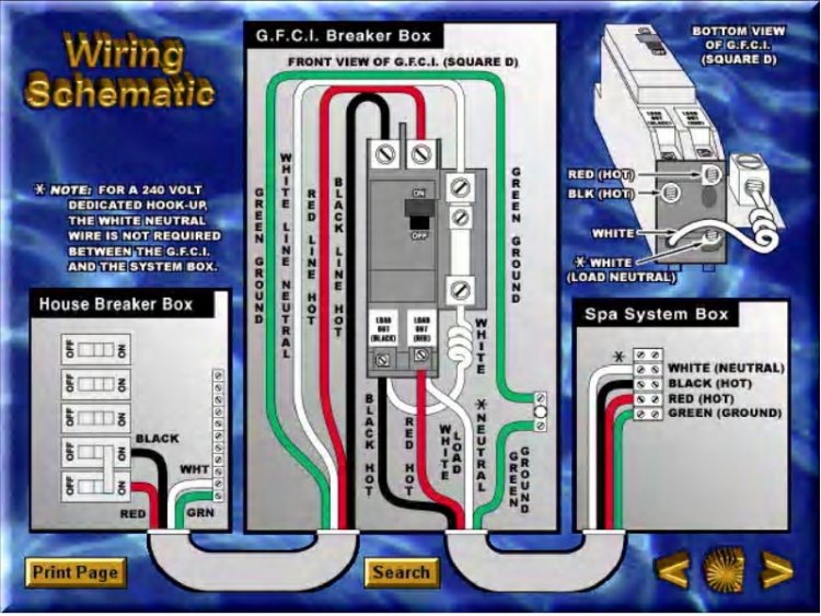
Spa Gfci Wiring Diagram Wiring Diagram Data Schema