In many of todays vehicles the ballast resistor is not needed. Note that the colors of the wires shown in the diagram below are at the module itself.

Repair Guides Engine Electrical Electronic Ignition System Coil
The wires in the harness tend to be different colors on different cars and years.
Ford ballast resistor wiring diagram.
The job of the ballast resistor was to inhibit current to a level that would not overheat the coil.
Our secure website and shopping cart allows you to shop with ease and be confident that your information is safe.
Resistors wiring diagrams duration.
Ford started using the ballast resistor wire with the 1960 models.
How to wire a doorbell diy live demo and wiring diagram duration.
2 wires wrong on ballast resistor 351w wiring lively projects.
For 1961 1967 ford econoline ballast resistor smp 29344vk 1964 1962 1963 1965 fits.
Listed below is a excellent image for ford ignition resistor wire wiring diagramwe have been looking for this image throughout web and it originated from reliable resource.
1956 through 1959 ford products had a separate wire wound resistor ballast screwed to the fire wall.
Of course this meant that there was going to be a little less power getting to the coil.
Measure the resistance of the primary ballast resistor with an ohmmeter.
This simple system is easy for even the novice mechanic to wire.
Value was 135 ohms nominal which would provide about 6 volts to the ignition coil during run conditions.
This video explains how the ballast resistor works.
Skip to main content.
Determine if ballast resistor is needed.
Ford 1966 ballast resistor.
For payment we accept mastercard visa discover american express and paypal.
Find great deals on ebay for ford ballast resistor.
Guaranteed by tue jun.
Modifying resistor plug to non resistor plug diy.
Sometimes wiring diagram may also refer to the architectural wiring program.
Remember the key must be off when this test is performed or power in.
Connecting a ballast resistor is a fairly straightforward project but you will want to pay attention to the wiring.
Ford ignition resistor wire wiring diagram may 14 2019 thank you for visiting here.
Wiring the duraspark ii.
The simplest approach to read a home wiring diagram is to begin at the source or the major power supply.
The typical automotive ignition system prior to 1974 consisted of a coil and ballast resistor with breaker points to interrupt the current flow when a spark was needed.
1950 ford 8n old start duration.
The wiring diagram on the opposite hand is particularly beneficial to an outside electrician.

Pertronix Wiring Resistor Wire Ford Falcon Ballast Resistor

Ignition Coil Wiring Diagram Chevy How To Wire A Points Connect

Ballast Resistor Wiring Diagram 69 Camaro Oil Pump Wiring Diagram
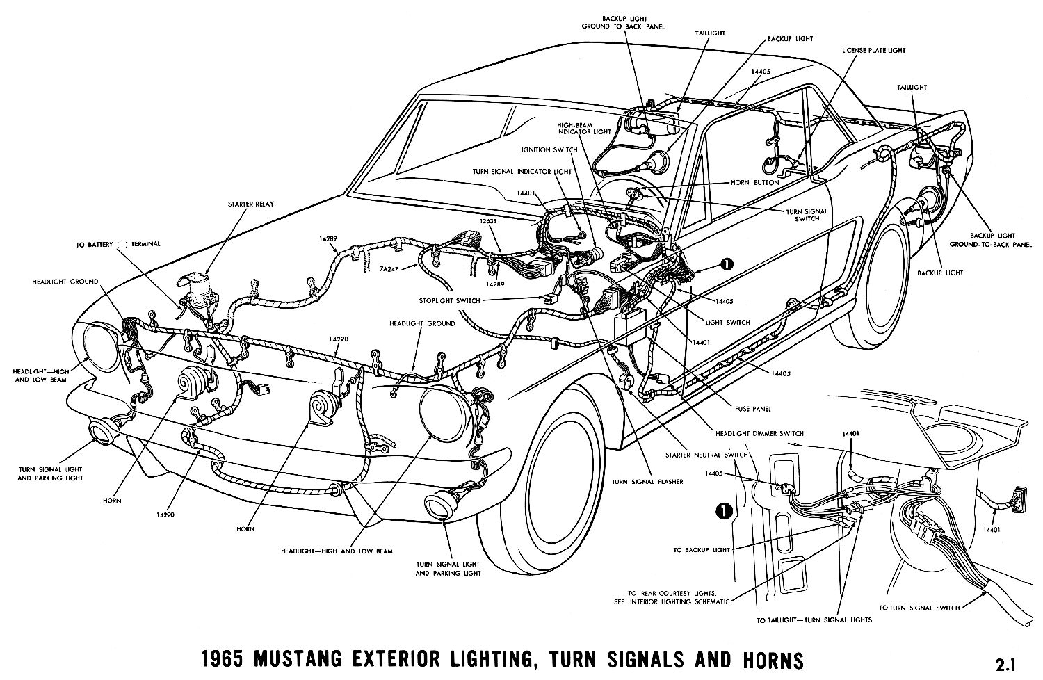
1965 Mustang Wiring Diagrams Average Joe Restoration

Ford Wiring Symbols Schematic Diagram Tractor Diagrams Find O H

Ford Pinto Ignition Wiring Diagram Wiring Library

Wiring Diagram On Ignition With Ballast Resistor Wiring Diagram

1965 Ford Mustang Wiring Diagram Lovely 1965 Ford Mustang Wiring

Repair Guides Engine Electrical Electronic Ignition System Coil
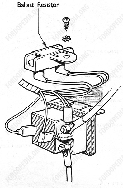
Fordopedia Org

Gm Hei Distributor Wiring Diagram Ballast Resistor Better Wiring

Ford Blower Motor Resistor Wiring Diagram Replacing Circuit With

4 Pin Ballast Wiring Diagram Basic Electronics Wiring Diagram

Ballast Resistor Wiring Diagram Online Wiring Diagram

Ballast Resistor Wiring Diagram Online Wiring Diagram