Or you are a student or maybe even you who simply wish to know regarding wiring diagram single phase motor contactor. Single phase motor starter wiring diagram collections of 3 phase motor starter wiring diagram pdf.

Single Pha Motor Reversing Contactor Wiring Original Forward Reverse
Circuit however the wiring diagram does not show the connections in a manner that can be easily followed.

Schematic contactor wiring diagram single phase.
A simple circuit diagram either of the two start buttons will close the contactor either of the stop buttons will open the contactornote that one one of the contactor acts as a switch for the start button.
3 phase motor contactor wiring diagram collections of wiring diagram kontaktor best circuit diagram contactor best 3.
For this reason a rearrangement of the circuit elements to form a line diagram is desirable.
3 phase motor starter wiring diagram sample.
Wiring diagram for motor contactor best wiring diagram motor fresh.
Wiring a single phase motor through a 3 phase contactor.
3 phase motor starter wiring diagram pdf.
Electrical wiring for single phase motor controls tobi a motor control is simply a relay contactor that acts as a switch which is activated by a different power source or a control circuit.
Home about us news wiring a single phase motor through a 3 phase contactor.
Weg wiring diagram single phase motor and 3 start stop to motors.
Weg motor starter wiring diagram image.
Wiring diagram for the motor save wiring diagram for single phase.
The line diagram sometimes referred to as an elementary diagram or a schematic diagram is.
You are right below.
Single phase power is typically reserved for lower power requirements however in some cases powering a small motor with single phase input power is practical.
The control circuit may be operated manually or automatically when the control circuit is wired through sensors or other control devices.
Some motors allow both 120 volt and 240 volt wiring by providing a combination of wires for doing so.
Residential power is usually in the form of 110 to 120 volts or 220 to 240 volts.
Searching for details regarding wiring diagram single phase motor contactor.
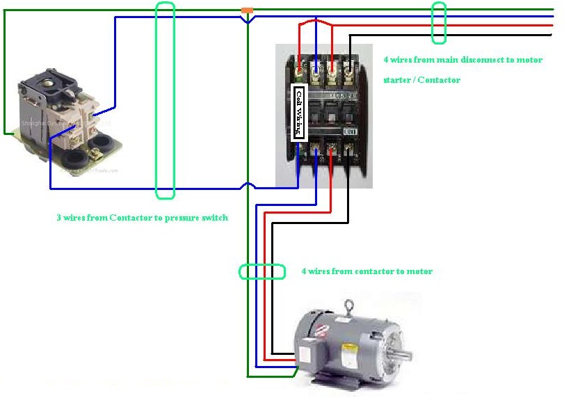
The above diagram is a complete method of single phase motor wiring with circuit breaker and contactor.
Wiring a motor for 230 volts is the same as wiring for 220 or 240 volts.
You may be a professional who intends to look for recommendations or address existing issues.
Posted january 18 2018 by springercontrols.
In the above one phase motor wiring i first connect a 2 pole circuit breaker and after that i connect the supply to motor starter and then i do cont actor coil wiring with normally close push button switch and normally open push button switch and in last i do connection between capacitor.
Single phase motors are used to power everything from fans to shop tools to air conditioners.
Wiring capacitors resistors semiconductors table 1 standard elementary diagram symbols contd iron core air core auto iron core air core current dual voltage thermal magnetic single phase 3 phase squirrel cage 2 phase 4 wire wound rotor armature shunt field show 4 loops series field show 3 loops commutating or compensating field show 2.

Phase Power Wiring Moreover Lighting Contactor Wiring Diagram

How To Wire Motor Control Contactor
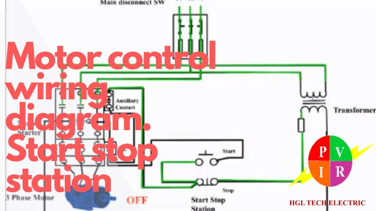
Motor Control Start Stop Station Motor Control Wiring Diagram How

240v Contactor Wiring Diagram Data Schema

A Three Pole Contactor Wiring Basic Electronics Wiring Diagram

Forward Reversing Magnetic Starter Schematic Marvelous Index 378

Relay Contactor Wiring Diagram Online Wiring Diagram
How To Wire A Contactor And Overload Direct Online Starter Youtube

Contactors Wiring Diagram Wiring Diagram Read

Wiring Diagram Eaton Wiring Diagram Schematics Contactor Picture

54 Inspirational Single Phase Motor Wiring Diagram Pictures Wiring
3 Phase Contactor Control Wiring Basic Electronics Wiring Diagram

Single Phase Motor Circuit Diagram Lovely Three Phase Contactor

Packard 2 Pole Contactor Wiring Diagram Online Wiring Diagram

120 Volt Photocell Wiring Diagram Wiring Schematic Diagram 104