Extrapolate the same expansion for additional axles. These 2 wire diagrams fit the needs for most trailers.
How To Wire Trailer Lights Trailer Wiring Guide Videos
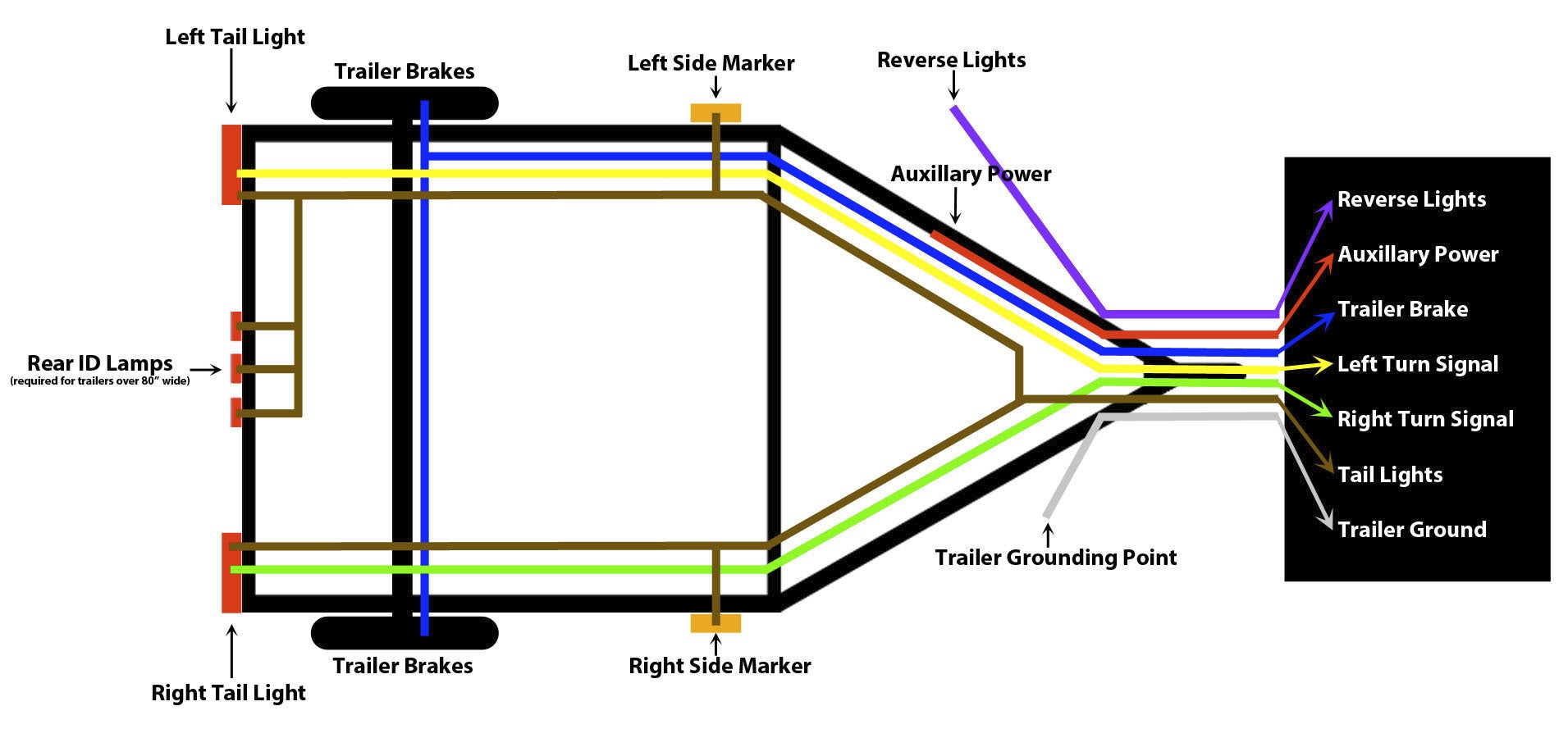
The image above shows a single axle trailer and the next image shows wiring for tandem axles.
Wiring schematic trailer lights.
If the trailer lights flicker on and off there is a good chance the trailer is grounding by way of the hitch instead of through the trailers wiring connector.
Begin by cleaning the ground connections.
Only the blue brake and white ground wires are different.
Trailer connectors are used between the two to allow disengagement when not.
Trailer wiring diagrams about us.
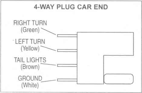
4 way flat molded connectors allow basic hookup for three lighting functions.
Trailer wiring diagrams 4 way systems.
Typical trailer wiring diagram and schematic.
Once or twice a year anyway and i just cannot keep the color code right ect whiteground brn running lights grn right turn yellow left turn.
Right turn signal stop light green left turn signal stop light yellow taillight license side marker brown and a ground white.
Each component should have its own ground to the frame of the trailer.
Below is the generic schematic of how the wiring goes.
Ground problems are the top cause of issues with trailer wiring.
To connect the electric system of your trailer to the vehicle you will be using special connector.
Please help me get it right.
Above we have describes the main types of trailer wiring diagrams.
4 pin trailer wiring diagram.
By law trailer lighting must be connected into the tow vehicles wiring system to provide trailer running lights turn signals and brake lights.
Standard color code for wiring simple 4 wire trailer lighting.
Various connectors are available from four to seven pins that allow for the transfer of power for the lighting as well as auxiliary functions such as an electric trailer brake controller backup lights or a 12v power supply for a winch or interior trailer lights.
Trailer wiring diagrams trailer wiring connectors various connectors are available from four to seven pins that allow for the transfer of power for the lighting as well as auxiliary functions such as an electric trailer brake controller backup lights or a 12v power supply for a winch or interior trailer lights.
If there are absolutely no provisions for trailer lights you are electrically inclined or have a rough idea of how to wire trailer lights you might consider splicing into your existing wiring.
This is accomplished by tapping into the tow vehicles electrical harness to transfer power to the trailer wiring system.

Solved I Need Wiring Diagram For 1995 Ford Ranger Xlt I Fixya

Lift Master Sensor Wiring Schematic Diagram For A Light Switch With

F350 Wiring Schematics Or Ford Wiring Diagram For Trailer Plug 58

Dirt Bike Wiring Schematic Diagrams For Car Audio Diagram Trailers

How To Connect 7 Way Trailer Rv Plug Diagram Video Aj S
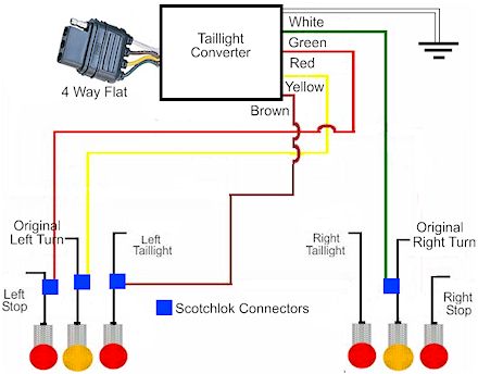
How To Install A Trailer Light Taillight Converter In Your Towing

Trailer Light Wiring Typical Trailer Light Wiring Diagram

Ranger Boat Wiring Diagram Vmglobal Co

Trailer Wiring Diagram Lights Brakes Routing Wires Connectors
Trailer Wiring Diagrams Johnson Trailer Co

Wiring Diagrams

Trailer Light Wiring Kit Tokyoalone Info

4 Wire Trailer Plug Diagram Data Schema

240v Water Heater Wiring Diagram Schematic For Three Way Switch
Plug Wiring Diagram Load Trail Llc