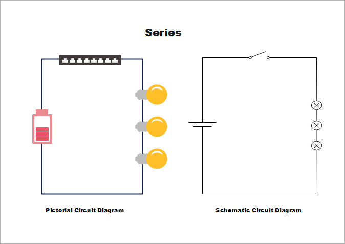
Unlike a pictorial diagram a wiring diagram uses abstract or simplified shapes and lines to show components. Most troubleshooters prefer schematic diagrams.

Basic Schematic Wiring Diagram Online Wiring Diagram
Using the same example as above the wiring diagram includes r1 from the schematic but instead of being on the far left it is depicted in the middle which is its actual location on the circuit board.

Wiring diagram vs schematic.
As nouns the difference between schematic and diagram is that schematic is a drawing or sketch showing how a system works at an abstract level while diagram is a plan drawing sketch or outline to show how something works or show the relationships between the parts of a whole.
A schematic illustrates how a circuit works logically.
It shows the components of the circuit as simplified shapes and the power and signal connections between the devices.
Creating draft versions of single line and schematic diagrams is part of the process of working out the final design aspects.
In a schematic circuit diagram the presentation of electrical components and wiring does not completely correspond to the physical arrangements in the real device.
Schematic is a synonym of diagram.
Wiring diagrams show how the wires are connected and where they should located in the actual device as well as the physical connections between all the components.
This gives a good explanation of the difference between a schematic and wiring diagram.
How is a wiring diagram different from a pictorial diagram.
A wiring diagram shows how wires and components are connected but not necessarily in logical order.
With some pictures this can give more detail information wiring diagram you will make.
A wiring diagram usually gives information about the relative position and arrangement of devices and terminals on the devices to help in building or servicing the device.
We hope that by posting this awesome wiring diagram.
Many installers prefer wiring diagrams.
As a adjective schematic.
Schematic diagrams show the network of contacts a network that can be extremely complex and the relays and motors that those contacts actuate.
For example 120 volt relay logic is still in widespread use in nuclear plants.
Wiring diagrams for circuits use the same labels as the schematic.
A wiring diagram is a simplified conventional pictorial representation of an electrical circuit.
This awesome wiring diagram vs schematic pics this may be the best choice for your inspiration.
Or you can search for a more searchable search through the search box that is in the top corner of this web.
A schematic circuit diagram represents the electrical system in the form of a diagram that shows the main features or relationships but not the details.

Build Your Own Arduino Bootload An Atmega Microcontroller
Filter Design Guide

Jeep Liberty Wiring Schematic Wiring Diagram

Wiring Schematics Height Off Floor Online Wiring Diagram

Jeep Liberty Wiring Schematic Wiring Diagram

Wiring What S A Schematic Compared To Other Diagrams

Electrical Wiring Diagrams For Schematics Online Wiring Diagram

Aviation Headset Plug Wiring Schematics Online Wiring Diagram
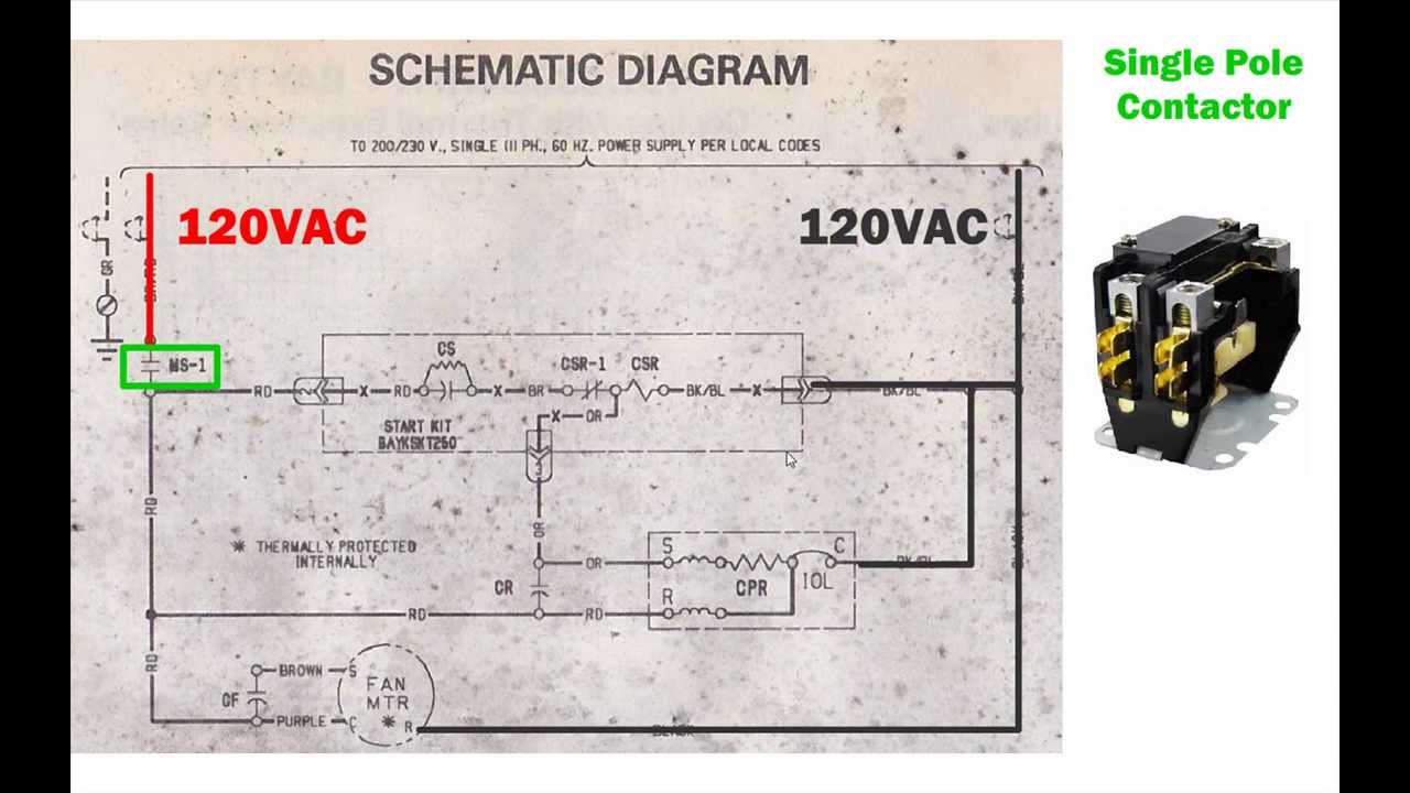
Hvac Condenser How To Read Ac Schematic And Wiring Diagram Air

2012 Mack Fuse Diagram Wiring Schematic Online Wiring Diagram

8 Pin Relay Socket Diagram Wiring Schematic Online Wiring Diagram
Schematics Com Free Online Schematic Drawing Tool
Difference Between Schematics And Circuit Diagrams

Jets Wiring Harness Schematic Online Wiring Diagram

Schematics Com Free Online Schematic Drawing Tool