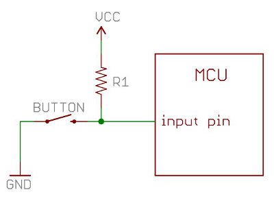
Two terminals of the device are connected to both the ends of the track. Attach the same way that you did with the resistor.

C4500 Blower Motor Wiring Diagram Wiring Diagram Data Schema
A wiring diagram is a simplified conventional pictorial representation of an electrical circuit.
Wiring diagram resistor.
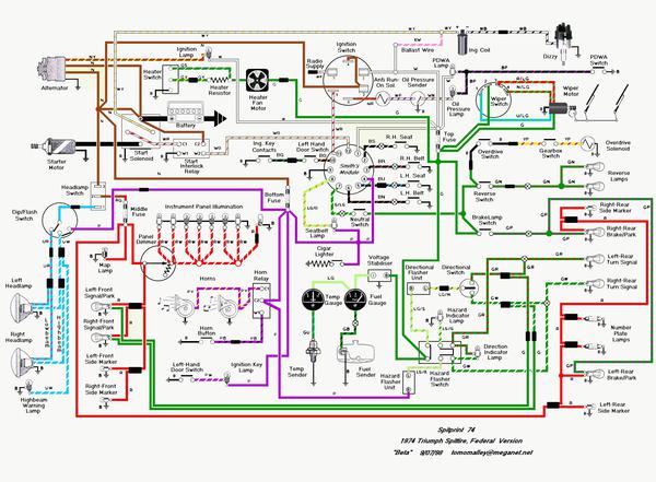
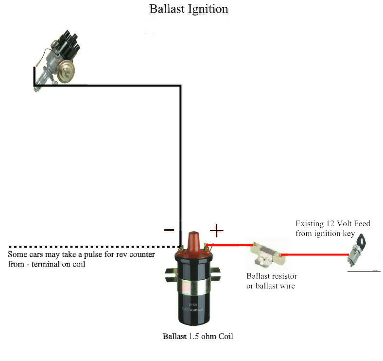
The typical automotive ignition system prior to 1974 consisted of a coil and ballast resistor with breaker points to interrupt the current flow when a spark was needed.
Electrical symbols electronic circuit symbols of schematic diagram resistor capacitor inductor relay switch wire ground diode led transistor power.
Connect your neck pickup to the pigtail labeled n and your bridge pickup to the pigtail labeled b.
Working of variable resistor.
The third terminal is connected to a wiper that decides the motion of the track.
This simple system is easy for even the novice mechanic to wire.
Each wiring diagram is shown with a treble bleed modification a 220kw resistor in parallel with a 470pf cap added to the volume pots.
As shown in the diagram below a variable resistor consists of a track which provides the resistance path.
Arduino light dependent resistor wiring diagram for ldr and led picture of wiring diagram installing led load resistor wiring harness in a bmw 4 wire fan switch diagram wiring for blower motor resistor diagrams schematics co ceiling.
Collection of 2006 chevy silverado blower motor resistor wiring diagram.
We use cookies to give you the best possible experience on our website.
It reveals the elements of the circuit as streamlined shapes and also the power and signal connections between the gadgets.
Resistors ohm s law electronics textbook.
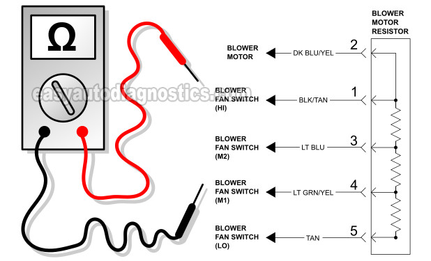
Wiring diagramthe blower resistor for the heater ac blower motor answered by a verified jeep mechanic.
Es 335 prewired standard assembly p gmod 6.
With the installation of the ballast resistor completed start the engine and let it run.
Once it is located on the firewall connect the negative wire from the ignition to the terminals.
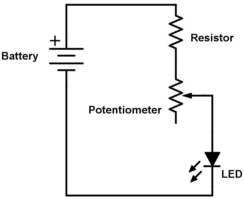
A potentiometer or pot for short is also known as a variable resistor.
The job of the ballast resistor was to inhibit current to a level that would not overheat the coil.
Run another wire from the condenser to the negative on the coil.
By continuing to use this site you consent to the use of cookies on your device as described in our cookie policy unless you have disabled them.
Variable resistors are used to dynamically change the resistance to control the current in a circuit and may also be used as a voltage divider.
New 1971 Spitfire Wiring Diagram Gt6 Triumph Wiring Diagram Data

Repair Guides Distributor Ignition System Diagnosis And Testing

H Wiring Diagrams Fundacaoaristidesdesousamendes Com

Chevy Coil Wiring Diagram Wiring Diagram

Delco Remy Alternator Wiring Diagram With Ac And Download 4 Wire
Low Voltage High Resistance Grounding System Basics C Hrg Technical
Heater Relay Wiring Diagram Wiring Diagram Data Schema

Bmw E46 Aux Cable Wiring Diagram Wiring Diagram Data Schema

How To Install Load Resistors For Led Turn Signal Lights 6 Steps
Blower Motor Resistor Wiring Diagram Online Wiring Diagram
Resistors Learn Sparkfun Com

Sr20 Wiring Diagram New Sr20det Ignitor Coil Resistor Red Blue Wire
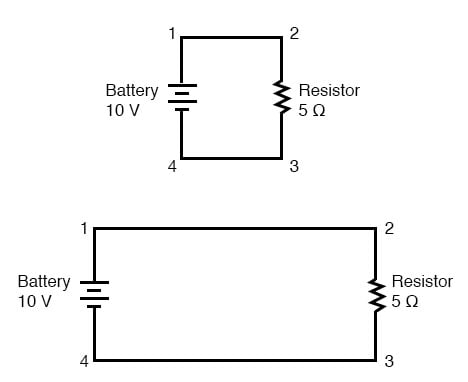
Circuit Wiring Ohm S Law Electronics Textbook
Variable Resistor Wiring Basic Electronics Wiring Diagram
Accuspark Wiring Diagrams