You are right below. Mostly used to regulate the current flow by addingsubtracting resistance from the circuit these resistors are available in many shapes and sizes.
Potentiometer Working Circuit Diagram Construction Types
How a potentiometer works options for wiring duration.
Wiring diagram potentiometer.
Potentiometers more commonly known simply as pots are a type of electrical component called a variable resistor.
Heres how to make one using a potentiometer.
Drives service support powerflex 40 wiring diagrams.
Searching for details concerning potentiometer wiring diagram.
Potentiometer working circuit diagram construction types.
Or you are a trainee or maybe even you who simply would like to know regarding potentiometer wiring diagram.
Wiring a potentiometer made simple youtube.
Its used in circuits a lot such as to control the volume of music equipment control the brightness of a light and much more.
The humble potentiometer or pot as it is more commonly known is a simple electro mechanical transducer.
How to wire a potentiometer.
It converts rotary or linear motion from the operator into a change of resistance and this change is or can be used to control anything from the volume of a hi fi system to the direction of a huge container ship.
Variable resistors are useful for the following.
They usually function in conjunction with a knob.
Humbucker strat tele bass and more.
You might be a technician that wishes to look for references or solve existing troubles.
The user turns the knob and this.
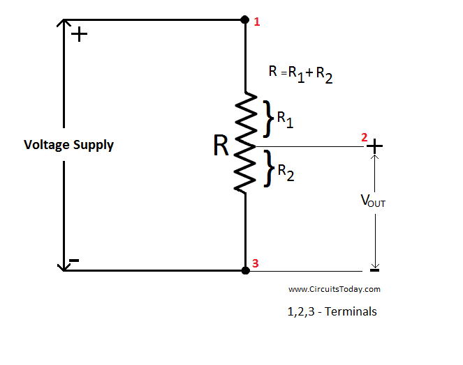
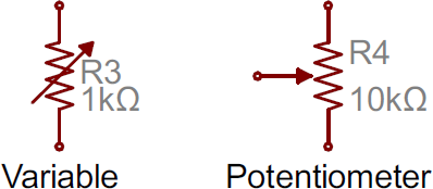
A potentiometer is a three terminal resistor with a sliding or rotating contact that forms an adjustable voltage divider.
The potentiometer is a handy little component that you really should know how to use.
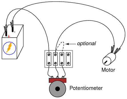
A quick video on how to wire a potentiometer to vary voltage for your project needs.
At some point in an electronics project you might find yourself needing a variable resistor.
Instructions for potentiometer wiring.
Wire a potentiometer as a variable resistor.
If only two terminals are used one end and the wiper it acts as a variable resistor or rheostat.
For this experiment you will need a relatively low value potentiometer certainly not more than 5 kw.
These resistors can be.
Lessons in electric circuits volume 1 chapter 2.
Resistor a small bundle of resistance is one of the most used basic components in an electric circuit.
The measuring instrument called a potentiometer is essentially a voltage divider used for measuring electric potential voltage.
Ohms law schematic diagram.
The component is an implementation of the.
Adjustable gain of an amplifier adjustable cutoff freque.
Wiring illustration for using a potentiometer as a rheostat.
The worlds largest selection of free guitar wiring diagrams.

Axl Guitar Wiring Diagram Pdf Epub Library

Schematic Diagram Of Manual Potentiometer Image And Video Exchange
Linear Potentiometer Wiring Diagram Online Wiring Diagram

3 Wire Potentiometer Diagram Basic Electronics Wiring Diagram

A Potentiometer Schematic Circuit Diagram Download Scientific Diagram

Guitar Wiring Diagram No Pots Online Wiring Diagram
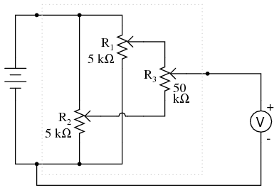
Precision Potentiometer Dc Circuits Electronics Textbook

How To Wire A Potentiometer Cerca Con Google Electronics Hobby

Electronics Basics How A Potentiometer Works Random Nerd Tutorials

Schaller S Megaswitch Diagram And Pinout Guitarnutz 2 Diagram Data

Wiring Diagram How To Wire A 12 Volt Relay Wiring Diagram 1997 Dodge
Potentiometer As A Rheostat Dc Circuits Electronics Textbook

How To Add A Raspberry Pi Potentiometer Howchoo

Mm 3000 Joystick Wiring Diagram Wiring Diagram
How To Read A Schematic Learn Sparkfun Com