It reveals the elements of the circuit as streamlined forms and the power and signal connections between the tools. Contactor and overload wiring diagram bestharleylinksfo.
Auto Transformer Diagram Motor Repalcement Parts And Diagram
Assortment of motor starter wiring diagram pdf.

Wiring diagram motor starter.
Figure 1 is a typical wiring diagram for a three phase magnetic motor starter.
Start stop 3 wire control.
Variety of 3 phase motor starter wiring diagram.
A wiring diagram is a simplified standard photographic depiction of an electric circuit.
Basic wiring for motor control technical data.
Motor starter schematic and wiring diagram.
Wiring diagrams bulletin 609 manual starters are operated by start.
They show the relative location of the components.
It shows the elements of the circuit as streamlined shapes and the power and signal links in between the tools.
Furnas motor starter wiring diagram gallery how to wire a shop.
A typical starter solenoid has one small connector for the starter control wire the white connector in the photo and two large terminals.
See how the anti.
Two speed manual motor starter is designed for starting protecting small single phase two speed ac fan motors.
Tesys u combination motor starter.
The starter solenoid works as a powerful electric relay.
One for the positive battery cable and the other for the thick wire that powers the starter motor itself see the diagram below.
If you have a 120v coil instead of running a line from coil overload l2 you must run coil overload neutral.
3ph starter3ph motor line voltage control three phase 3ph motor starter controlling a three phase motor rev 08 aug 2006 the above wiring diagram assumes your magnetic starter has a 240v coil.
Motor starting switches and wiring diagrams for ac manual starters drum switches starters contactors relays limit switches and lighting contactors.
Wiring diagram book square d 8501 type nr socketswell guard pump panelsdefinite purpose contactors 8910square d nema relay.
They can be used as a guide when wiring the controller.
A wiring diagram is a streamlined standard pictorial representation of an electric circuit.
Wiring diagram contactor relay new refrence wiring diagram for.
Figure 1 typical wiring diagram.
Learn to navigate this systems wiring circuitry and diagram using current flow analysis relay and module operation and neutral switch actuation such as circuit completion.
Starting a three phase motor.
A type od part v.
A wiring diagram gives the necessary information for actually wiring up a group of control devices or for physically tracing wires when trouble shooting is.

120v Motor Wiring Diagram Wiring Diagram Document Guide

Ac Motor Control Circuits Ac Electric Circuits Worksheets
3 Phase Star Delta Wiring Diagram Wiring Schematic Diagram 36
Hitachi Starter Motor Wiring Diagram Wiring Diagram Data Schema

Square D Motor Starters Wiring Diagram Design Templates

Siemens Pad 3 Wiring Diagram Wiring Diagram Document Guide

Three Phase Motor Starter Wiring Diagram Online Wiring Diagram
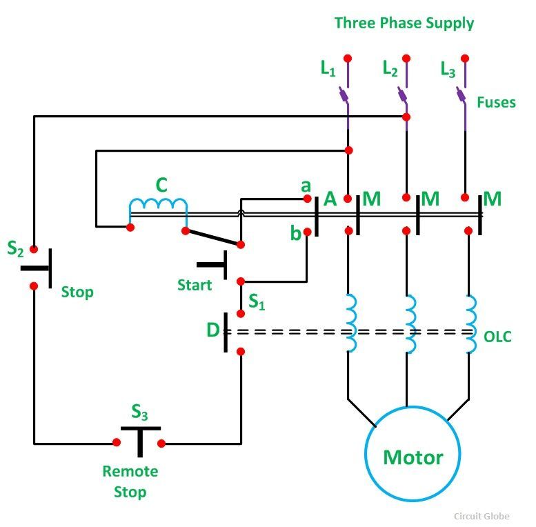
What Is Direct On Line Starter Its Theory Of Starting Circuit Globe

Autotransformer Motor Starter Wiring Diagram Basic Electronics

Auto Transformer Diagram Motor Repalcement Parts And Diagram

Nema Motor Wiring Diagram Basic Electronics Wiring Diagram

Combination Motor Controller Wiring Diagram Wiring Diagram Data Schema

Manual Motor Starter Wiring Diagram Wiring Diagram

Relay And Motor Wiring Diagram Electronic Design Diagram Data Schema
Ds80 Wiring Diagram Basic Electronics Wiring Diagram