Wiring diagram for 7 prong trailer plug wiring diagram for 7 pin trailer connector wiring diagram for 7 pin trailer plug wiring diagram for 7 pin trailer plug australia people understand that trailer is a vehicle comprised of quite complicated mechanisms. Wire can be used for brake control or auxiliary.

Trailer Connectors In Australia Wikipedia
Wiring diagram for ifor williams trailer lights best ifor.
Wiring diagram for trailer plug.
When shopping for trailer connectors remember that the male end is mounted on the vehicle side and the female on the trailer side.
6 way systems round plug.
If you are local to us give us a call if you want to schedule a time to have your trailer fixed.
The 7 pin n type plug and socket is still the most common connector for towing.
7 way trailer rv plug diagram.
7 way trailer plug wiring diagram ford collections of wiring diagram rv 7 way plug refrence 7 wire trailer wiring diagram.
Trailer plug connector diagrams for electrical towing connectors.
If you can not figure out your wiring even after reading this guide then contact your local mechanic or trailer shop for help.
The trailer wiring diagrams listed below should help identify any wiring issues you may have with your trailer.
Trailer wiring diagrams.
Car trailer wiring diagram uk new best ford 7 way trailer plug.
This automobile is designed not just to travel one place to another but also to carry heavy loads.
Round 1 14 diameter metal connector allows 1 or 2 additional wiring and lighting.
This supplies power to the road lighting of your trailer or caravan.
Can also be used as custom wiring on trailers with 3 lightwire systems.
This has now been replaced by 13 pin euro plugs on all new caravans.
Use on a small motorcycle trailer snowmobile trailer or utility trailer.
7 way plug wiring diagram standard wiring post purpose wire color tm park light green battery feed black rt right turnbrake light brown lt left turnbrake light red s trailer electric brakes blue gd ground white a accessory yellow this is the most common standard wiring scheme for rv plugs and the one used by major auto manufacturers today.
Various connectors are available from four to seven pins that allow for the transfer of power for the lighting as well as auxiliary functions such as an electric trailer brake controller backup lights or a 12v power supply for a winch or interior trailer lights.
View diagrams for our 4 way 6 way 7 way plugs.
Below is a diagram for the original plug and socket showing the functions of each pin.
If you are looking at the inside of the trailer connector where the wires mount to the terminals starting at the notch at the top and working clockwise.
7 way trailer plug wiring diagram gmc wiring diagram collection.
We have an excellent wiring diagram on our website i will provide you a link so you can look at it.
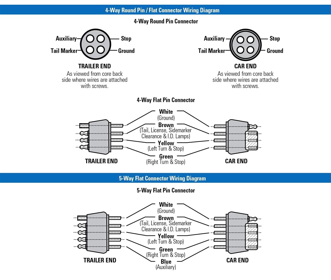
When wiring a trailer connector it is best to wire by function as wire colors can vary.
This guide is here to help you.

Wire Lights Diagram Online Wiring Diagram
Reese 4 Wire Trailer Wiring Diagram Diagram Data Schema

Semi Truck Trailer Wiring Online Wiring Diagram

7 Pole Wire Diagram Basic Electronics Wiring Diagram

4 Pin Plug Wiring Diagram Online Wiring Diagram

Box Trailer Wiring Harness Wiring Diagram Data Schema

4 Way Trailer Wiring Diagram Online Wiring Diagram

6 Pin Round Wiring Diagram Online Wiring Diagram

7 Pin Flat Trailer Plug Wiring Diagram Nz Archives Nostoc Co

Truck Trailer Wiring Harness Online Wiring Diagram

Trailer Caravan Electrical 12n Normal Wiring Diagram
Plug Wiring Diagram Load Trail Llc

Led Trailer Light Wiring Diagram Wiring Diagram Data Schema

Trailer Plug Wiring Diagram In Trailer Hitch Wiring Diagram 7 Pin

7way In 7 Plug Trailer Wiring Diagram Wiring Diagram