The following trailer wiring diagrams and explanations are a cross between an electrical schematic and wiring on a trailer. Various connectors are available from four to seven pins that allow for the transfer of power for the lighting as well as auxiliary functions such as an electric trailer brake controller backup lights or a 12v power supply for a winch or interior trailer lights.

1995 Ford F250 Trailer Wiring Diagram Online Wiring Diagram
A wiring diagram is a streamlined traditional photographic depiction of an electric circuit.
Trailer wiring schematics.
If you can not figure out your wiring even after reading this guide then contact your local mechanic or trailer shop for help.
A wiring diagram is a streamlined conventional pictorial representation of an electric circuit.
The trailer wiring diagrams listed below should help identify any wiring issues you may have with your trailer.
Above we have describes the main types of trailer wiring diagrams.
That said for specific situations there are industrial standards with different connectors and wire arrangements.
Trailer wiring diagrams trailer wiring connectors various connectors are available from four to seven pins that allow for the transfer of power for the lighting as well as auxiliary functions such as an electric trailer brake controller backup lights or a 12v power supply for a winch or interior.
4 pin trailer wiring diagram.
Below is the generic schematic of how the wiring goes.
We recommend these standards because they are pretty universal.
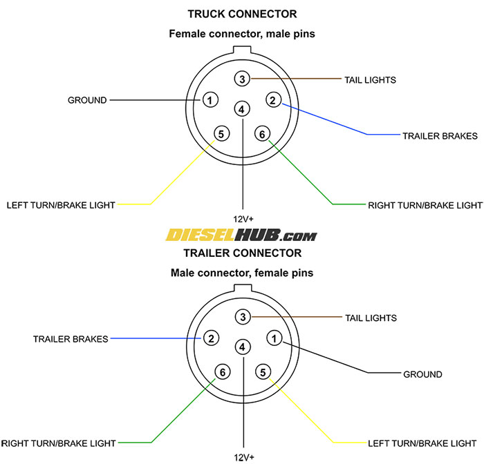
7 way plug wiring diagram standard wiring post purpose wire color tm park light green battery feed black rt right turnbrake light brown lt left turnbrake light red s trailer electric brakes blue gd ground white a accessory yellow this is the most common standard wiring scheme for rv plugs and the one used by major auto manufacturers today.
Collection of travel trailer wiring schematic.
Assortment of electric trailer brake wiring schematic.
This guide is here to help you.
To connect the electric system of your trailer to the vehicle you will be using special connector.
7 way trailer rv plug diagram.
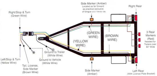
Right turn signal stop light green left turn signal stop light yellow taillight license side marker brown and a ground white.
It reveals the parts of the circuit as streamlined shapes as well as the power and also signal links in between the gadgets.
4 way flat molded connectors allow basic hookup for three lighting functions.
When shopping for trailer connectors remember that the male end is mounted on the vehicle side and the female on the trailer side.
It reveals the parts of the circuit as streamlined forms as well as the power and signal connections in between the gadgets.
Trailer wiring diagrams 4 way systems.
If you are local to us give us a call if you want to schedule a time to have your trailer fixed.
Standard Seven Pin Wiring Diagram Online Wiring Diagram
Trailer Wiring Diagram For 4 Way 5 Way 6 Way And 7 Way Circuits

Wiring Diagram 4 Plug Pin Trailer Online Wiring Diagram

Flat Four Trailer Wiring Diagram Online Wiring Diagram

4 Way Trailer Wiring Diagram 2007 Trail Wiring Diagram Data Schema

Toyota 4 Pin Trailer Wiring Harness Online Wiring Diagram
Plug Wiring Diagram Load Trail Llc

Rv Trailer Wiring Schematic Online Wiring Diagram

2010 Jeep Liberty Trailer Wiring Diagram Online Wiring Diagram

Carry On Dump Trailer Wiring Diagram Wiring Diagram Data Schema

2012 Toyota Tundra Wiring Online Wiring Diagram

4 Way Trailer Wiring Diagram Online Wiring Diagram
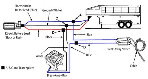
Trailer Breakaway Wiring Schematic Online Wiring Diagram

Tundra Trailer Wiring Harness Removal Online Wiring Diagram

Trailer Wiring Diagram Lights Brakes Routing Wires Connectors