Wound rotor motors can be started with low inrush current by inserting high resistance into the rotor circuit. Three phase motor control installation wiring diagrams lcsc electronic components more asian brands lower prices.
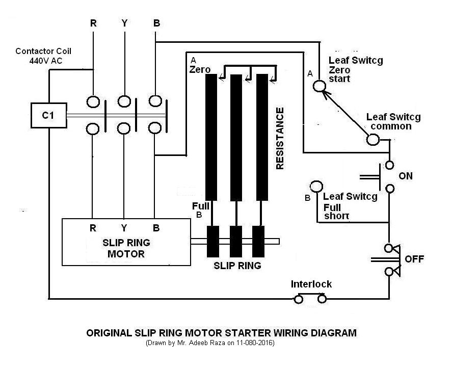
Slip Ring Motor Starter Adeeb S Space
Adjusting the resistance allows control of the speedtorque characteristic of the motor.

Slip ring motor starter wiring diagram.
But how does external resistance aid in better starting characteristics.
Discuss your questions and problems.
Three phase slip ring rotor starter control diagram control diagram.
Cage motor is thus preferred to a slip ring motor.
Three phase slip ring rotor starter control power diagrams.
These motors are practically always started with full line voltage applied across the stator terminals.
To join our whatsapp group click on the link.
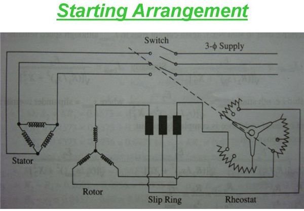
Read here to know about the starting arrangement and the role played by the external resistances in obtaining better starting characteristics.
A slip ring induction motor can be started with external resistance added in its rotor circuit.
Wiring diagram slip ring motor business wire heidenhain corporation is proud to take part in the ltn specializes in providing slip ring and resolvers to international machine builders and factory automation industries.
O because a slip ring motor is used primarily to start a high inertia load or a load that requires a very high starting torque across the full speed range slipring motors are best utilised but not.
Check more diagrams here.
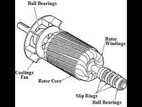
A wound rotor motor is a type of induction motor where the rotor windings are connected through slip rings to external resistance.
As the motor accelerates the resistance can be decreased.
Starting of slip ring motors.
You may also read.
Available with clockwise or counterclockwise synchron gear motors or hansen brush type dc gear motors for use in any position.
A simple circuit diagram of contactor with three phase motor.
The value of starting current is adjusted by introducing a variable resistance in the rotor circuit.
In fact the start up torque can be.
In this video you will learn connection of slip ring motor with starter panel now you can join our whatsapp group.
Three phase motor power control wiring diagrams 3 phase motor power control wiring diagrams three phase motor connection schematic power and control.
In a current limiting method the closing of contactors at each step is.
A slip ring motor also requires a larger space for the motor and its controls.
Also know about the qualities of slip ring induction motors.
By switching on a starter resistor in any phase of the rotor winding the start up torque can be changed.
52 starting of slip ring motors these can be started by adopting either a current limiting method or a definite time control method.

Three Phase Slip Ring Rotor Starter Control Power Electrical

Motor Starter Diagram Feat Pictures Single Phase Motor Starter

Audi Wiring Diagrams Online Diagram Symbols Car Uk Series Broadband
Impressive Slip Ring Motor Starter Wiring Diagram Slip Ring Motor

Slip Ring Motor Connection Diagram Jeido Org
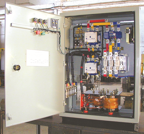
Magna Start New Generation Slip Ring Motor Starter Electrical

What Are Slip Rings And Why Do Some Motors Use Them
Slip Ring Youtube

Electrical And Instrumentation Engineering Why Is Star Delta
Slip Ring Motor Wiring Diagram Soft Starter Slip Ring Photos Slip

What Are The Type Of Starter Used For Slip Ring Induction Motor Quora
Brake Test On A Three Phase Slip Ring Induction Motor
Starting Of Slip Ring Induction Motor Explained In An Easy Manner

Manual Speed Controllers For Wound Rotor Induction Motors

Slip Ring Motor Liquid Resistor Soft Starting System Hv Lrs