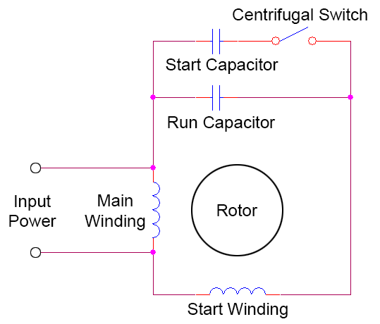
Start capacitor run capacitor or permanent capacitor. These designs operate by creating a rotating magnetic field.

Single Phase Motor Wiring Diagrams 120 Volt Up Down And Railex
Single phase motor wiring diagram with capacitor baldor single phase motor wiring diagram with capacitor single phase fan motor wiring diagram with capacitor single phase motor connection diagram with capacitor every electric arrangement is made up of various diverse parts.
Single phase motor wiring diagram with capacitor start.
There are a multitude of single phase motor combinations.
Some single phase ac motor designs use motor run capacitors which are left connected to the auxiliary coil even after the start capacitor is disconnected by the centrifugal switch.
Wiring single phase induction motors capacitor and repulsion start.
Single phase motor connection with capacitor in hindi e l.
Wondering how a capacitor can be used to start a single phase motor.
Frequent stopstarts andor changing of the direction of rotation will damage the motors capacitors and winding.
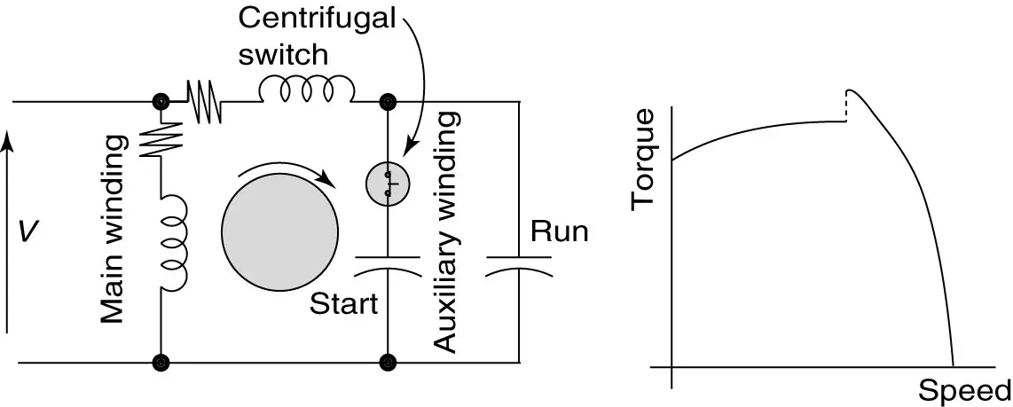
Also read about the speed torque characteristics of these motors along with its different types.
Lets start with the basic diagram of the motor.
How to wire single phase motor with capacitor.
Wiring diagram single phase motors 1empc permanent capacitor motors 1empcc capacitor start capacitor run motors.
Each part ought to be set and connected with other parts in specific way.
Soft start of induction motor by acpwm in this drive the load is connected in series with the input terminals of the bridge rectifier and its output terminals are connected to the pwm controlled power mosfet igbt or bipolar or power transistor.
A single phase motor starter wiring diagram is shown in the below figure.
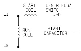
Click here to view a capacitor start motor circuit diagram for starting a single phase motor.
Learn how a capacitor start induction run motor is capable of producing twice as much torque of a split phase motor.
There are a number of single phase motors on various pieces of equipment and what i will try to do here is to explain it as easily as possible.
This text will discuss only five basic designs.
Three phase motors with single phase frequency inverter should be used for frequent onoff switching.
You will find out how to identify to main and auxilliary winding and change motor rotation.
Single phase motor starting in addition to the run or main winding all induction single phase motors are equipped with an.
We have had a look at motor testing on the three phase motors and i think we should also have a quick look at the single phase connection diagram.

How Does A Rotating Magnetic Field Occur In Motors Supplied With A

Start Motor Wiring Diagram Wiring Diagram Data Schema
Ac Motor Capacitor Wiring Online Wiring Diagram

Single Phase Motor Wiring Diagram With Capacitor Wiring Diagram
Single Phase Capacitor Start And Capacitor Run Electric Motor
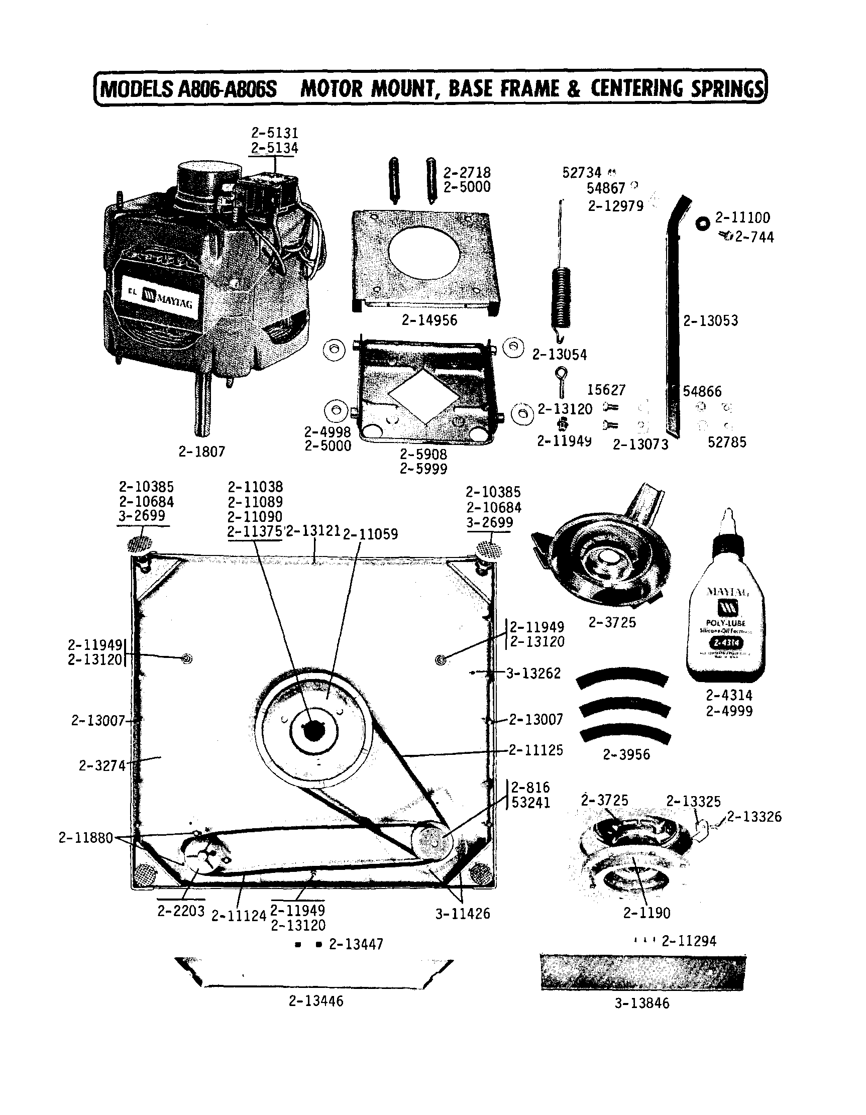
Single Motor Circuit Diagram Motor Repalcement Parts And Diagram

Types Of Single Phase Induction Motors Single Phase Induction
How To Reverse The Rotation Of Single Phase 220v Motor Quora
Terminal Markings And Internal Wiring Diagrams Single Phase And
Types Of Single Phase Induction Motors Single Phase Induction
Terminal Markings And Internal Wiring Diagrams Single Phase And

220 Single Phase Wiring Diagram Http Shdesignsorg Welding Cp250 Cp

1ph Motor Wiring Diagram Online Wiring Diagram

Two Phase Motor Wiring Diagram Basic Electronics Wiring Diagram

Capacitor Start Run Induction Motor Electrical Schemaw