Electrical wiring for single phase motor controls tobi a motor control is simply a relay contactor that acts as a switch which is activated by a different power source or a control circuit. May 19 2019 single phase motor wiring with contactor diagram.

Wiring Contactors Diagram Online Wiring Diagram
How to control single magnetic contactor with push button how to control single starter in urdu how to control single starter with push button single phase motor starter connection control.
Single phase contactor wiring diagram with timer.
A complete guide of single phase induction motor wiring connection with magnetic contactor or stater.
Draw a diagram showing when mechanical gears are used the motor shaft runs in one direction and the gears for forward and reverse engage and disengage according to the.
Wiring capacitors resistors semiconductors table 1 standard elementary diagram symbols contd iron core air core auto iron core air core current dual voltage thermal magnetic single phase 3 phase squirrel cage 2 phase 4 wire wound rotor armature shunt field show 4 loops series field show 3 loops commutating or compensating field show 2.
Some motors allow both 120 volt and 240 volt wiring by providing a combination of wires for doing so.
I had to do this a few times with floodlights to be used outside.
The control circuit may be operated manually or automatically when the control circuit is wired through sensors or other control devices.
A simple circuit diagram either of the two start buttons will close the contactor either of the stop buttons will open the contactornote that one one of the contactor acts as a switch for the start button.
Wiring a motor for 230 volts is the same as wiring for 220 or 240 volts.
Single phase motors are used to power everything from fans to shop tools to air conditioners.
In this video i enplane how to wire a magnetic contactor or starter for single phase motor.
Break your circuit l n e through your contactor.
Single phase motor wiring with contactor diagram.
In the above one phase motor wiring i first connect a 2 pole circuit breaker and after that i connect the supply to motor starter and then i do cont actor coil wiring with normally close push button switch and normally open push button switch and in last i do connection between capacitor.
The above diagram is a complete method of single phase motor wiring with circuit breaker and contactor.
Timer wiring diagrams single phase reversing motor relay on although across the line motor control circuits time to speed up another set of starter contacts bypass line power around the resistors directly to the motor windings.
Residential power is usually in the form of 110 to 120 volts or 220 to 240 volts.
Single phase motor wiring with contactor diagram.
Electric motor electrical engineering circuit brick hardware fans engine computer hardware bricks.
Link a permanent live and a neutral from your supply to your coil al a2 then use your switch feed to your photocell from a1 and switch the wire to the switched phase of your contactor load.
Discover ideas about electrical wiring diagram.
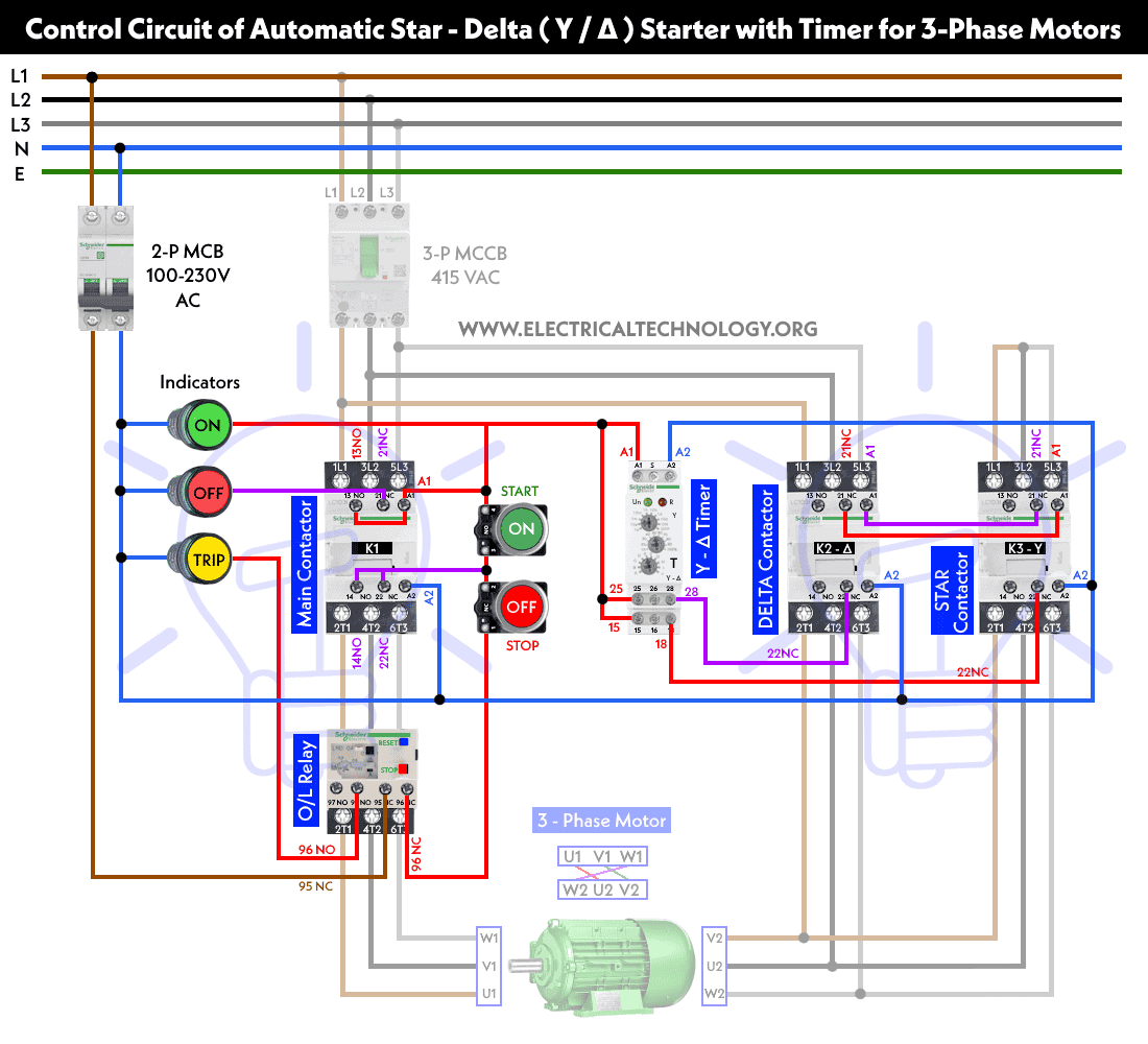
Star Delta Starter Y D Starter Power Control And Wiring Connection
Star Delta Starter Y D Starter Power Control And Wiring Connection

2 Pole Contactor Wiring Basic Electronics Wiring Diagram

How To Wire Motor Control Contactor

Timer To Contactor Wiring Diagram Motor Contactor Wiring Diagram

How To Install 3 Phase Timer

Motor Control Fundamentals Wiki Odesie By Tech Transfer

Contactor Wiring Diagram With Timer Basic Electronics Wiring Diagram

220v Pool Pump Motor On Electric Motor Single Phase Wiring Diagram

Timer And Contactor Wiring Diagram Pdf Switch Star Delta Paragon

Contactor Relay Wiring Diagram Wiring Diagram Document Guide
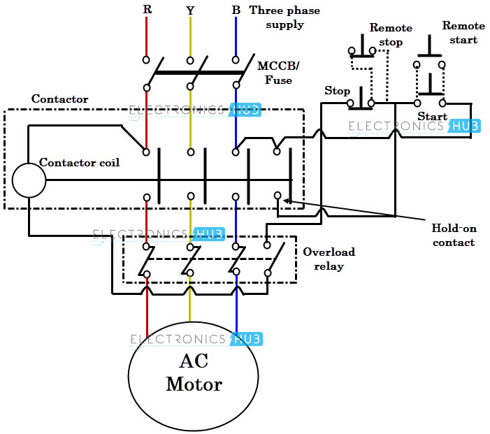
Direct Online Starter Dol Starter
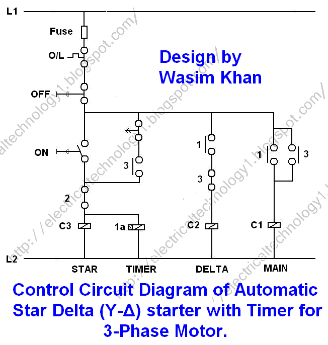
Star Delta Starter Y D Starter Power Control And Wiring Connection

Timer Relay 120v Wiring Diagram Circuit Diagram Template

Star Delta Starter Electrical Notes Articles