Check out the wiring examples at the end to see it in action. Out of its three terminals two of them are fixed and one a is a varying linear rotary terminal.
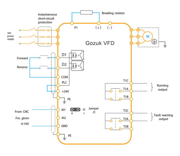
10k Potentiometer Wiring Vfd To Moreover Wiring A Potentiometer To A
A little later we shall look at the many ways a standard pot may be wired as well as some further.
Potentiometer wiring schematic.
Heres how to make one using a potentiometer.
They usually function in conjunction with a knob.
At some point in an electronics project you might find yourself needing a variable resistor.
You will see that many people insist on using zig zag lines for resistors and pots i dont and havent done do for at least 40 years so dont expect me to start again now.
Instructions for potentiometer wiring.
Potentiometers more commonly known simply as pots are a type of electrical component called a variable resistor.
It has three pins and the schematic symbol looks like this.
But while the resistance value of a resistor stays the same you can change the resistance value of a potentiometer by turning its shaft.
The user turns the knob and this.
However there are applications where we dont necessarily need a variable.
It is like the resistor.
You might be a technician that wishes to look for references or solve existing troubles.
Variable resistors are useful for the following.
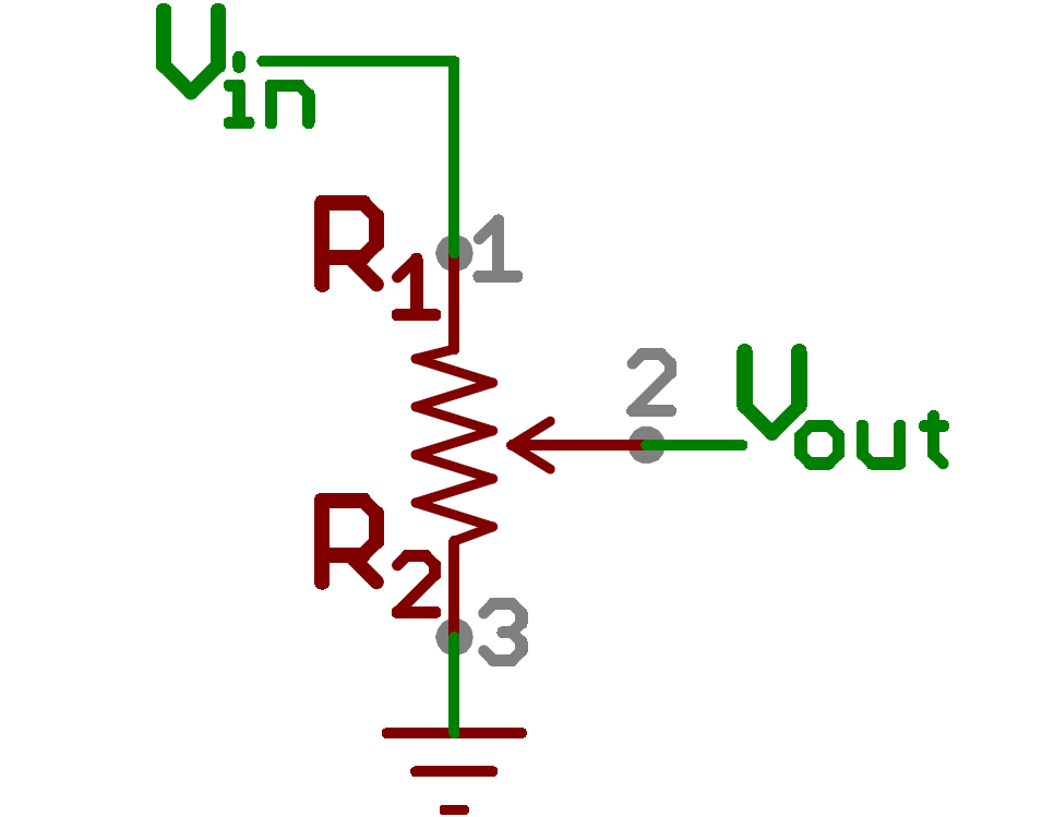
Potentiometers find their most sophisticated application as voltage dividers where shaft position determines a specific voltage division ratio.
This will give you something to refer to when reconnecting the wires control pots can usually be found under pickguards heres the basic concept well convert the wiring pot.
Searching for details concerning potentiometer wiring diagram.
User accessible rotary potentiometers can be fitted with a switch which operates usually at the anti clockwise extreme of rotation.
How to wire a potentiometer.
How to wire a potentiometer from a schematic before you disconnect the potentiometer draw a wiring diagram or take a photo.
The standard schematic symbol for a pot is shown to the left.
Or you are a trainee or maybe even you who simply would like to know regarding potentiometer wiring diagram.
Potentiometer pot the potentiometers or the aoepotsa as it is commonly known in the electric circles is a three terminal variable resistor.
Drives service support powerflex 40 wiring diagrams.
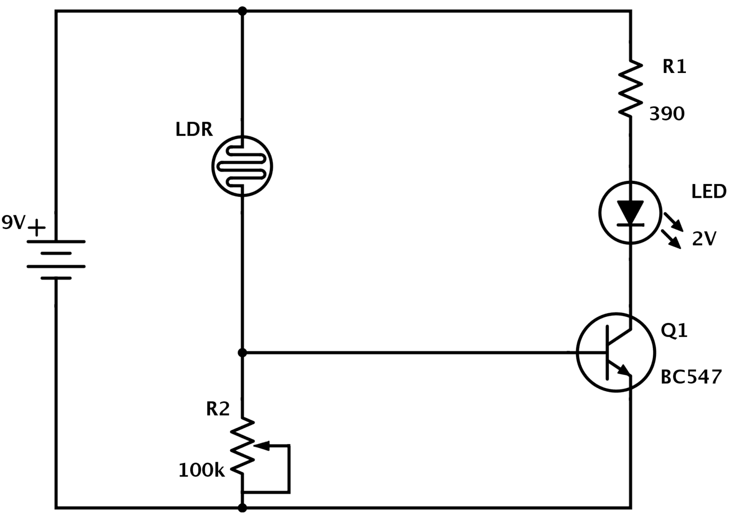
Wiring illustration for using a potentiometer as a rheostat.
You are right below.
A string potentiometer is a multi turn potentiometer operated by an attached reel of wire turning against a spring enabling it to convert linear position to a variable resistance.
What is a potentiometer.
Adjustable gain of an amplifier adjustable cutoff freque.
Wire a potentiometer as a variable resistor.

Sprecher Schuh Technical Tips

Using A Ds1802 Pushbutton Digital Potentiometer To Create An Audio
Ds1669 Digital Potentiometer

10k Potentiometer Wiring Vfd To Moreover Wiring A Potentiometer To A
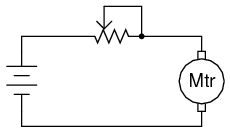
3 07 Potentiometer As A Rheostat Workforce Libretexts
Sparkfun Inventor S Kit Experiment Guide V4 0 Learn Sparkfun Com
Ac Potentiometer Wiring Wiring Library

Component Potentiometer Circuit Symbol Diagram Basics Electronic

Electronic Potentiometer Circuit

Integrated Circuit How Does A Digital Potentiometer Work

Guitar Wiring Ideas
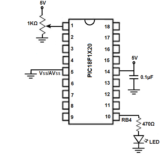
Pic Potentiometer Circuit

5 Pin Potentiometer Wiring Schematic Wiring Library C B Trailer

10k Pot Wiring Diagram Basic Electronics Wiring Diagram
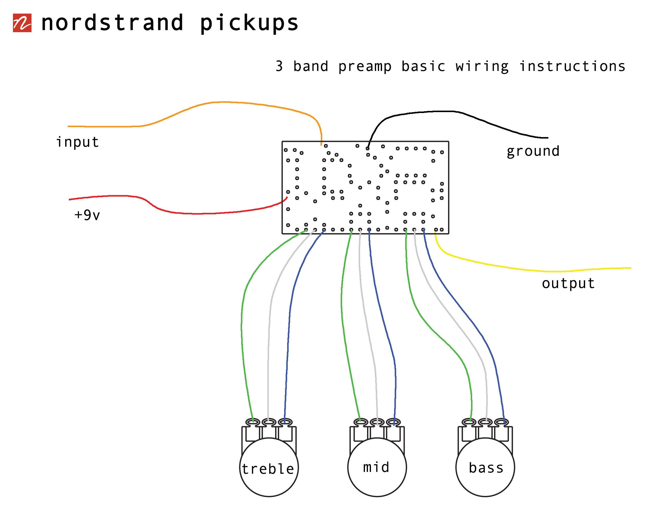
Potentiometer Wiring Diagram Nordstrand Blend Pot Diagram Diagram