However too small of a resistor or too large of a battery will cause the led to get hot and burn out. Load resistor installation instructions warning.
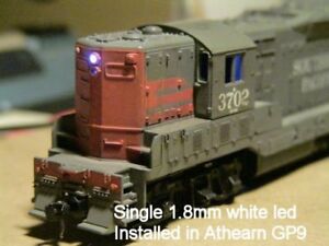
10 White 1 8mm Leds For Ho Scale Headlights Free Resistors Wiring
This video demonstrates how to install standard led resistors in order to slow down led turn signals.
Led resistor wiring diagram.
Sometimes wiring diagram may also refer to the architectural wiring program.
Do not install onnear painted surfaces or plastic.
Led load resistor wiring diagram load resistor instructions plasmaglow led productsled bulb bulb socket splice here splice here ground wire power wire load resistor using the diagram below splice the load resistors wires in so that it connects across the positive and negative wires of.
A replacement flasher has the added benefit of being plug and play requiring no modification whatsoever to your vehicle or its wiring.
Dont use a 50 watt resistor just because some guy on the internet tells you to.
The wiring diagram on the opposite hand is particularly beneficial to an outside electrician.
Load resistors are designed to get hot.
Larger resistors will cause the led to glow dimmer.
The simplest approach to read a home wiring diagram is to begin at the source or the major power supply.
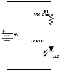
The 150 ohm resistor stopped enough of the 45v power supply from reaching the 17v led that it lit up safely and kept it from burning out.
The led calculator was great for single leds but when you have several the wizard will help you arrange them in a series or combined seriesparallel configuration.
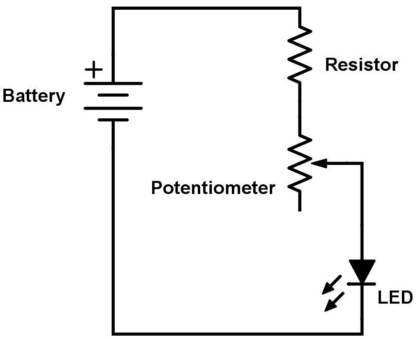
Vary the values of resistor used.
Give us a call with any questions 314.
Load resistors should be your very last resort if you cant find a replacement led flasher that will work with your vehicle.
If you have any questions leave a comment below and ill do my best to answer.
The wizard determines the current limiting resistor value for each portion of the array and calculates power consumed.
Whenever using a resistor on an led it should get placed before the led on the positive electrode.
Practical led indicator and flasher circuits from led load resistor wiring diagram source.
Led bulb bulb socket splice here splice here ground wire power wire load resistor using the diagram below splice the load resistors wires in so that it connects across the positive and negative wires of the vehicles turn signal bulb wiring.
Hopefully those looking for practical information on electrical circuits and wiring led components found this guide first.
Its likely though youve already read the wikipedia page about series and parallel circuits here maybe a few other google search results on the subject and are still unclear or wanting more specific information as it pertains to leds.
This video is a guide showing the proper way to wire led turn signal resistors.
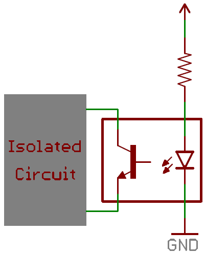
Led resistor capacitor circuit.
Low and behold the led lit up once again.
Smaller resistors will cause the led to glow brighter.
Resistors and led bulbs available from diode dynamics.

Led Load Resistors Wiring Diagram
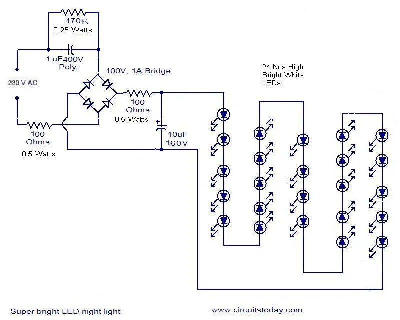
Mains Operated Led Circuit Electronic Circuits And Diagrams

How To Wire Led Tail Lights Lincoln Vs Cadillac Forums

Resistor Needed For Leds All About Circuits

How To Install Load Resistors For Led Turn Signal Lights 6 Steps

Breadboard Layout Arduino Lesson 2 Leds Adafruit Learning System
Resistor Wiring Diagram Wiring Diagram Data Schema

Led 110v Wiring Diagram Wiring Library
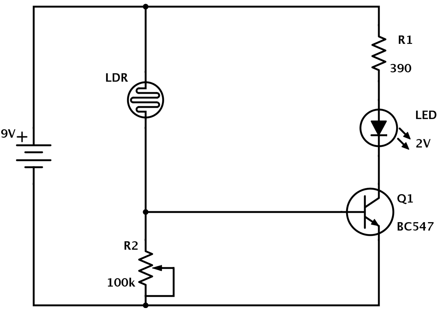
Automatic Street Light Control System Using Ldr Transistor Bc 547

How To Add Resistors For Led Tail Lights Chevy Colorado Gmc Canyon
Circuit Diagram How To Read And Understand Any Schematic
Diodes Learn Sparkfun Com

Led Resistor Wiring Diagram Wiring Diagram Data Schema
Types Of Resistors And How To Choose One
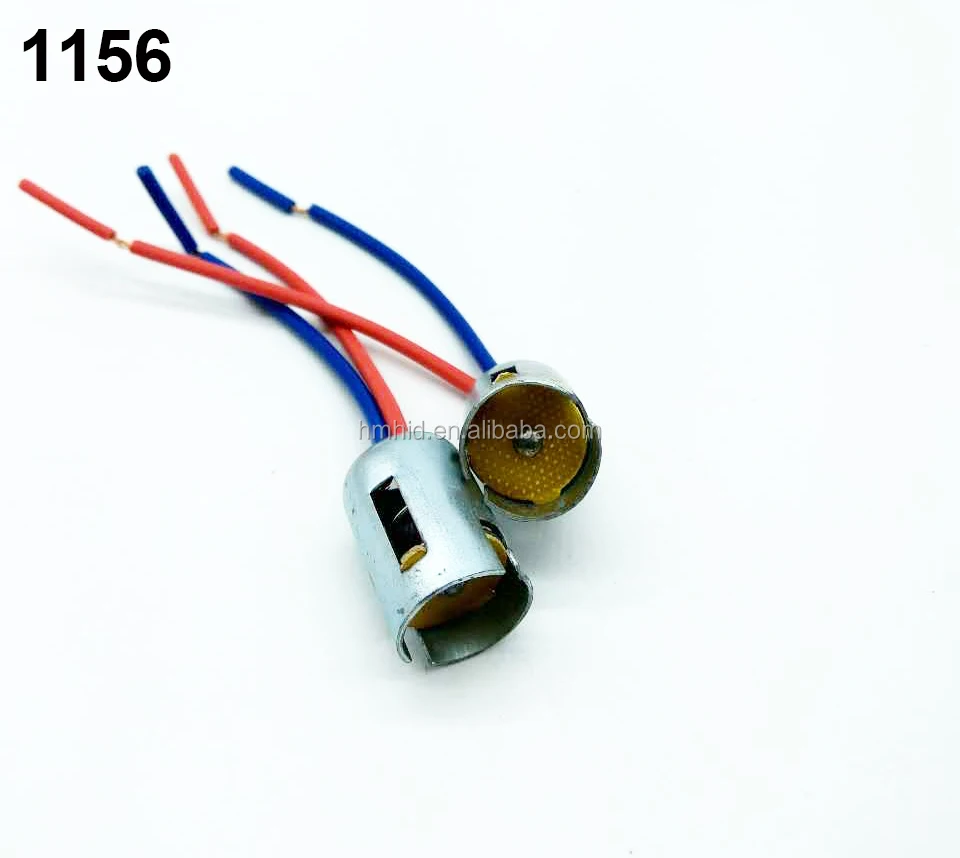
Pcs T10 1156 1157 T20 Wiring Socket For Led Signal Light Bulb Socket