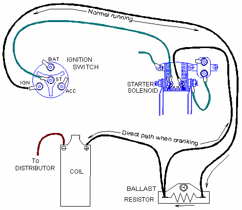
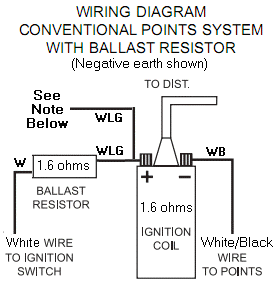
Black wire from distributor goes to the negative post on the coil. I disconnected and removed the ballast resistor and the little cannister thingy and just ran the positive wire directly to the ignition coil.

Ignition Coil Ballast Resistor Wiring Diagram Wiring Diagram
The resistor looking thing on the coil braket with a black wire coming out of it or ballast resistor should be wired in line.

Ignition coil ballast resistor wiring diagram.
For additional how to tutorials visit our website.
The typical automotive ignition system prior to 1974 consisted of a coil and ballast resistor with breaker points to interrupt the current flow when a spark was needed.
Years ago and i dont even remember why hrmph.
Yellow goes to the welll you know that already.
We have gathered lots of images ideally this photo is useful for you as well as aid you in locating the response you are looking for.
In the years when engines were a lot easier to work with a ballast resistor was used in order to prolong the life of the coil.
This video explains how the ballast resistor works.
If you have connected it this way and also connected the coil to battery the coil will be constantly drawing current and will overheat and also flatten the battery.
I drove it for years like that and last year in an effort to increase the spark i purchased an msd blaster 2 coil 8203 which does not require an external.
In a points type ignition the ballast resistor would help to keep the spark down and the coil from being burned up too quickly.
Diagram attached for wiring of points dizzy and coil with ballast resistor.
I dont know if it has a primary resistance wire.
This simple system is easy for even the novice.
I have looked up wiring diagrams online and havent seen any with a ballast resistor on the diagram.
Of course this meant that there was going.
The coil does not go direct to earth.
Im assuming they mean a ballast resistor.
Ignition coil ballast resistor wiring diagram welcome to my internet site this blog post will certainly discuss concerning ignition coil ballast resistor wiring diagram.
I picked up a new coil and it says use with primary resistance wire or external resistor.
The job of the ballast resistor was to inhibit current to a level that would not overheat the coil.
3 0 mercruiser ignition coil wiring diagram by yahutt mang december 15 2018 1994 ford probe diagram wiring diagram1995 box mercruiser 3 0 diagram 1 smo zionsnowboards de u2022 rh electrical system wiring diagrams ignition wiring diagram for mallory distributor 17 12mallory ignition box rh wierd firing order on 01 ford ranger 3 0v6 8171314689.

Ignition Troubleshooting
Coil Wiring Diagram Basic Electronics Wiring Diagram

Ballast Resistor Wiring Wiring Diagram

Ford Duraspark 2 Ignition Wiring On Duraspark 2 Wiring Diagram

Wiring Diagram To 1968 302 Wiring Diagram Data Schema

Case Vac Wiring Diagram Basic Electronics Wiring Diagram

Hei Connector Wiring Diagram Free Picture Schematic Wiring Diagram

B Body 1962 74 Charger Road Runner Super Bee Electrical

Ih 450 Wiring Diagram Wiring Diagram M6

Single Output Dyna Coil Wiring Diagram Wiring Diagram Data Schema

B Body 1962 74 Charger Road Runner Super Bee Electrical

Resistor Wire Diagram Wiring Diagram Tutorial

1998 Chevy Truck Wiring Diagram Wiring Diagram Data

6v Positive Ground Alternator Wiring Diagram Wiring Diagram Data

Simple Ignition Wiring Diagram Wiring Diagram