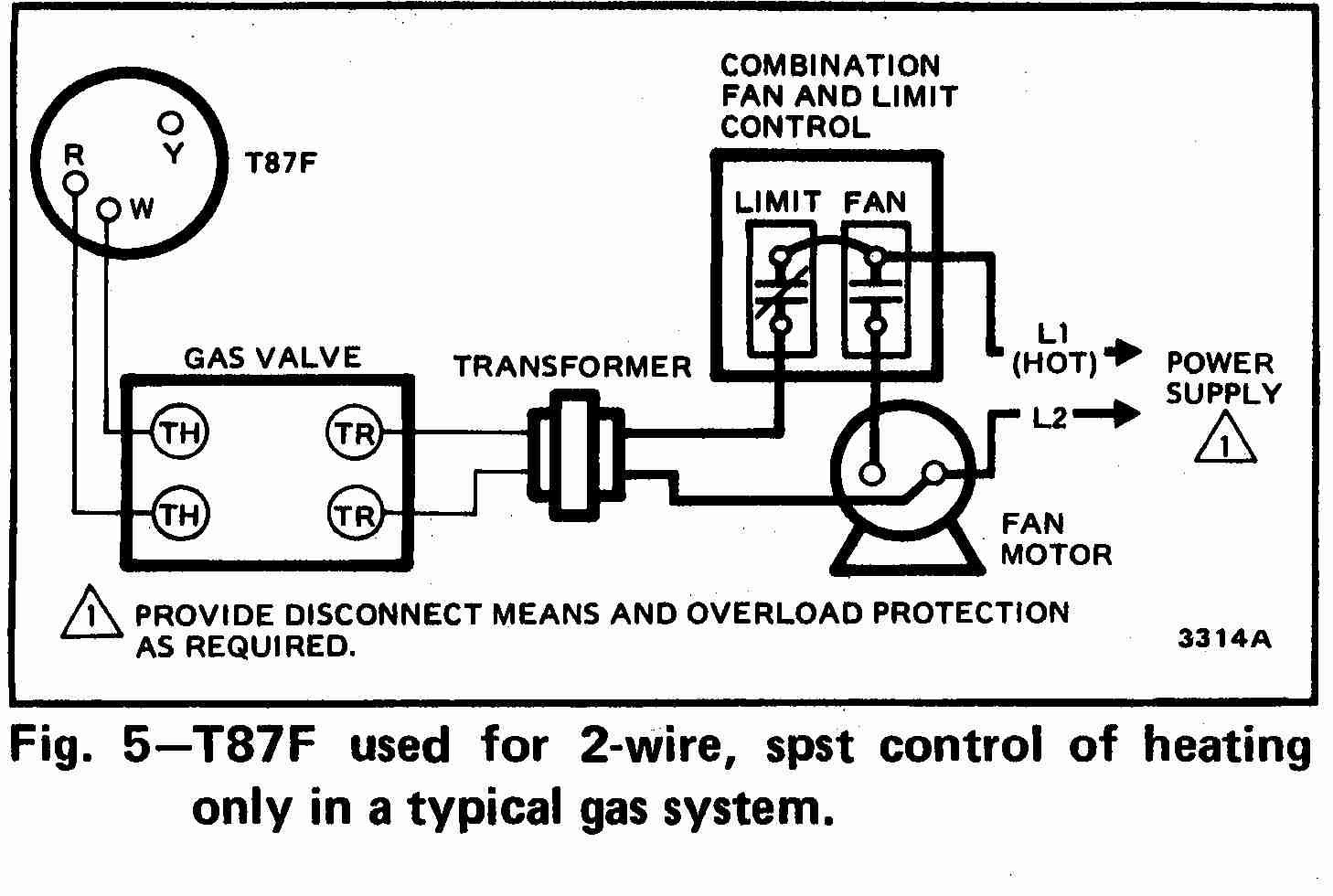
A wiring schematic shows the condition of a piece of equipment when there is no power being applied to the unit. Straight cool air conditioning condensing unit wiring practice electrical project 7 duration.
Electrical Wiring Diagrams For Air Conditioning Systems Part One
Thermostat wiring colors code high performance hvac thermostat terminal designations.

Hvac wiring schematic.
This article provides room thermostat wiring diagrams for flair honeywell white rodgers and other thermostat brands.
Schematic diagrams for hvac systems.
Electrical wiring diagrams for air conditioning systems part one.
Always follow safety instructions especially with electricity.
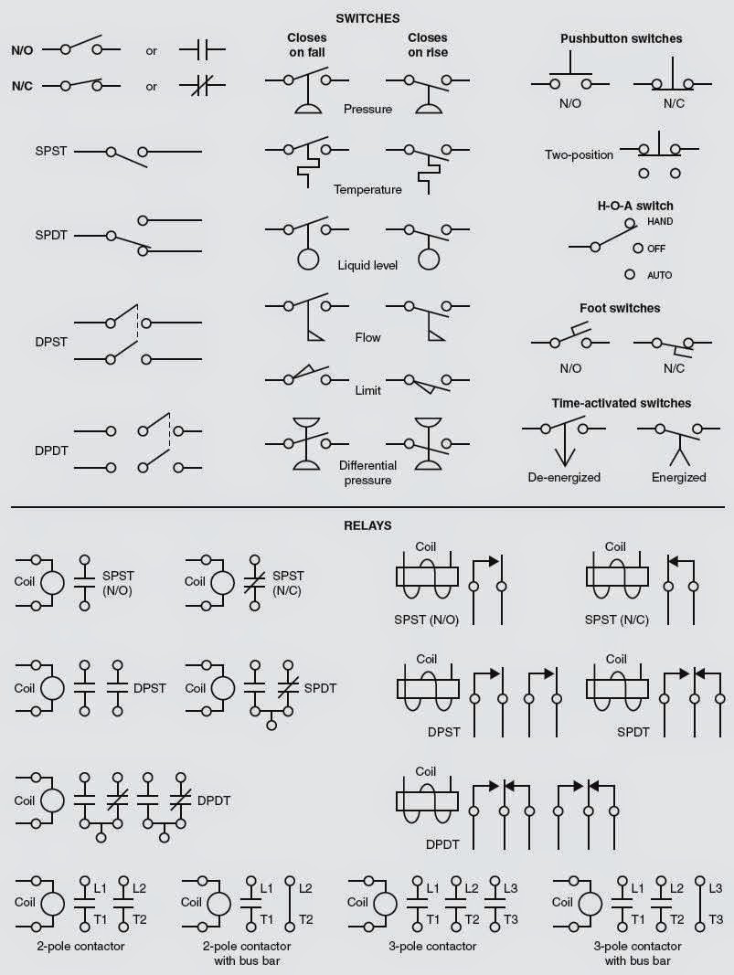
For example if a switch is depicted as being normally open no or normally closed nc remember that the position of the switch is shown as it appears when.
And in article electrical wiring diagrams for air conditioning systems part one i explained the following points.
Piece of hvacr equipment the problem tur ns out to be electrical in nature.
Schematic and ladder diagrams.
If you have a clear under standing of how to read wiring diagrams you fre quently can find the source of the trouble simply by checking the wiring of the unit itself against the man ufacturers wiring diagramthe purpose of this chap.
Inside those compact units are electrical connections fans compressors condensors switches coolantsthe list goes on and on.
B legend factory power wiring factory control wiring field control wiring field power wiring component connection field splice junction contactor capacitor dual run crankcase heater compressor compressor time delay indoor fan high pressure switch indoor.
For people who prefer to see an actual wiring schematic or diagram when wiring up a room thermostat those illustrations are provided here to help understand what wires are being connected and what each wire is doing.
What you need to know if you know a little bit about home heating and cooling systems you probably realize that they are pretty complicated little systems.
Wiring diagrams for hvac systems and other complicated electrical systems come in two major variations schematic diagrams and ladder diagrams.
This should be done at the circuit breaker for both the condenser and the air handlerfurnace.
Before you decide to change your thermostat make sure you have the correct tools especially a screwdriver and wire pliers.
Understanding hvac schematics 1 ron walker.
Turn the power off before proceeding.
Thermostat wiring diagrams heat pumps are wired for hvac control far differently than air conditioning systems so make sure you know the difference and correctly identify the type of hvac system you have installed.
Importance of electrical wiring for air conditioning systems.
Introduction for air conditioning systems types introduction for types of motorscompressors used in air conditioning systems.
Schematic diagram ladder form may be factory or field installed 319390 401 rev.
Unsubscribe from ron walker.

2008 Impala Wiring Diagram Hvac Online Wiring Diagram

Hvac Wiring Schematics Wiring Diagram Data Schema

Air Conditioner Schematic Diagram Figure 1 7 Air Conditioner Wiring

Basic Air Conditioner Wiring Diagram Wiring Diagram Data Schema
Room Thermostat Wiring Diagrams For Hvac Systems

2003 Silverado A C Controls Wiring Diagram Wiring Diagram Data Schema
Trane Xl14i Wiring Diagram Online Wiring Diagram

Basic Hvac Blower Wiring Wiring Diagram Data Schema

Old Carrier Wiring Diagrams Online Wiring Diagram

Rooftop Unit Schematic Wiring Diagram Data Schema

Freightliner Century Wiring Diagrams Online Wiring Diagram

Diagram Goodman Wiring Furnace Ae6020 Online Wiring Diagram

And Wiring Diagrams For Hvac Free Download Wiring Diagram Schematic

Goodman Air Handler Wiring Diagram Diagram Data Schema

Lennox Hvac Wiring Online Wiring Diagram