Refer to fan coil installation instructions for features and additional wiring information 2. The thermostat controls the operation of the heater compressor and blower as shown in figure 1.

Heat Pump Thermostat Wiring Diagram Fresh Hvac Thermostat Wiring
Thermostat terminal designations explanations.

Hvac low voltage wiring diagram.
Goodman heat pump low voltage wiring diagram collections of rheem heat pump thermostat wiring diagram collection.
Wiring low voltage wiring 230208v 1 phase and 3 phase are equipped with dual primary voltage transformers.
The voltage should be measured at the field power connection point in the unit and while the unit is operating at full load maximum amperage operating condition.
Low voltage transformer is connected through the thermostat to each control relay.
The voltage should be measured at the field power connection point in the unit and while the unit is operating at full load maximum amperage operating condition.
Diagram to use with unit and vents note.
How to identify each wire for an hvac for a thermostat thermostat wiring basics most thermostats send commands to your hvac system heat or air conditioning via low voltage wires inside a command box.
Table 1 diagram to use with unit and vents note.
Use our menu to the right to find helpful articles such as thermostat wiring diagrams low voltage circuits for hvac how to wire an air conditioner for control control board troubleshooting and thermostat troubleshooting.
Figure 1 is a circuit diagram showing the simplest possible known thermostat control system for heating and cooling operation of an ac and furnace or.
Wiring diagram notes 1.
Installing your low voltage two wire is very simple to do on an air conditioning condensing unit.
Hvac thermostat wiring diagram lovely wonderful carrier heating.
The heat source for a basic ac system can include heat strips for electric heat or even a hot water coil inside the air handler that is fed from a water heater.
Goodman heat pump wire colors thermostat wiring diagram package.
Wiring diagram for furnace new goodman heat pump low voltage.
Low voltage wiring diagrams thermidistat control.
Additional resources thermostat wiring colors code.
How to wire an air conditioner for control 5 wires the diagram below includes the typical control wiring for a conventional central air conditioning systemit includes a thermostat a condenser and an air handler with a heat source.
To activate dehumidify function on fk series remove j1 jumper at fan coil control board.
Heat pump must have a high pressure switch for dual fuel applications.
This is just a short refresher as to how easy.
Teap rang 2640v 253 21 2708v 220 18 wiring low voltage wiring 230208v 1 phase and 3 phase equipment dual primary voltage.

Wiring For Hvac In Every Symbol Wiring Diagram M6

Hvac Control Wiring Diagram Webtor Me

Air Conditioner Low Voltage Wiring Diagram Wiring Diagram
Electric Blanket Circuit Diagram Astonishing Wiring Schematic

Aac Unit Wiring Wiring Diagram
Choose The Right Thermostat
Hvac Low Voltage Wiring Wiring Diagram Data Schema
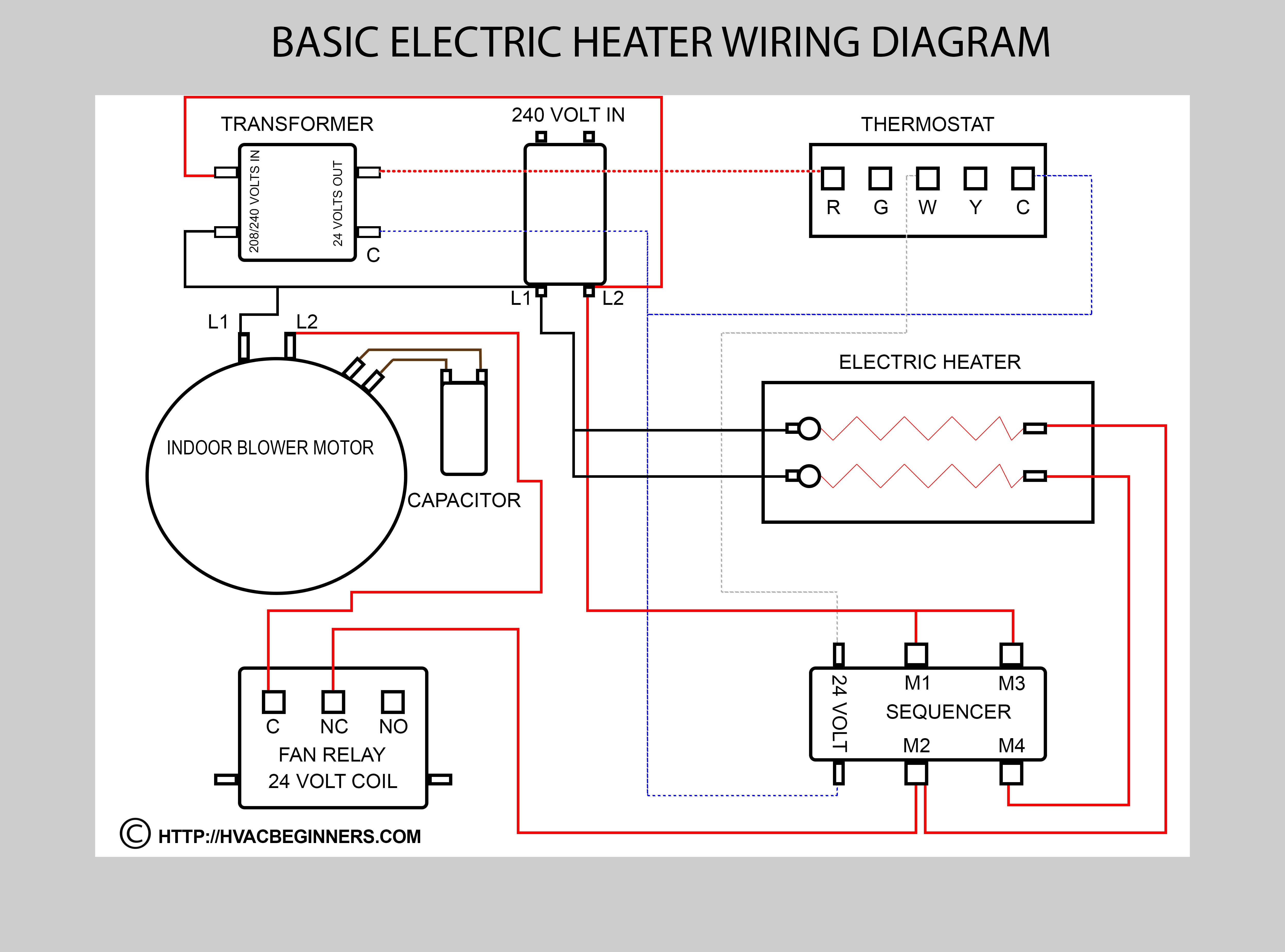
Hvac Training On Electric Heaters Hvac Training For Beginners

Wiring Diagram For Three Way Switch With Dimmer A Light Symbols

Best Central Air Conditioner Wiring Diagram For Library

Carrier Ac Air Handler Control Board Doityourself Com Community Forums

Thermostat Wiring Diagrams For Gas Packs Pdf Epub Library

Fan Limit Control Installation Faqs
Wiring Diagram Symbols Automotive Software Open Source Mac For A

Pioneer Deh 1100mp Wiring Diagram 2 Wiring Diagrams