The phone connector was invented for use in telephone switchboards in the 19th century and is still widely used. The phone connector is cylindrical in shape with a grooved tip to retain it.

Peltor Headset Wiring Diagram Online Wiring Diagram
The trs connector is also known as audio jack phone jack phone plug jack plug stereo plug mini jack mini stereo or headphone jack.

Headphone jack wiring schematic.
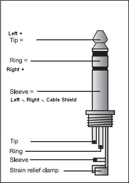
Below is a plug diagram and basic schematic including the typical terminal designations.
With a headphone jack insert a headphone plug with known wiring scheme and use an ohmmeter or continuity tester to match the jack connections to the plug.
Posted by circuit basics.
A phone connector also known as phone jack audio jack headphone jack or jack plug is a family of electrical connectors typically used for analog audio signals.
Headphone schematic diagram best place to find wiring and datasheet resources.
Headphone jacks are sold in open circuit and closed circuit versions.
Wiring diagram audio plug mono audio plug.
Wiring diagram 5 wire earphone jack wiring diagram databasemercruir wiring diagram charging and staring adequate wire wh1000xm2 sony.
What you are describing is hacking a headphone plug.
When reading the schematic think of the plug being inserted from left to right to align with the respective terminals of the mating jack.
You will just have no place to connect the microphone signal from the trrs wiring in the trs plug so you will lose the function of the microphone but will still have stereo audio as you correctly surmised.
Headphone jacks are frequently subjected to wear through their normal usage.
This wiring convention is common to all microphones that use this style of connector.
This video will demonstrate how to assemble an aircraft microphone and headphone jack.
Note that the schematic symbol for the microphone jack makes a distinction about which wire connects furthest out on the plug tip and which wire is between the tip and sleeve ring.
How to hack a headphone jack.
Basic drawing of an audio plug and jack schematic.
Headphone jack color code best place to find wiring and datasheetrca connector wiring diagram wiring diagram.
The open circuit jack is general purpose and has 3 pins for the left and right channels and ground.
The use of a soldering iron is required in order to complete this repair.
The following schematic shows the trs connector plug schematic diagram.
Most headsets will have different colored wiring.
Do not assume the colors shown on this schematic represent the colors of the wiring in your headset prior to to modification.
You must confirm the identity color of your audio and ground wires prior to making the wiring harness.
The proper way to connect and solder the jacks and the use of a solder sleeve to remote bondground the mic.
Instead of purchasing a new pair of headphones which can sometimes have a hefty cost replacing the connector is often a cheaper choice.
This specific example does not include switches.
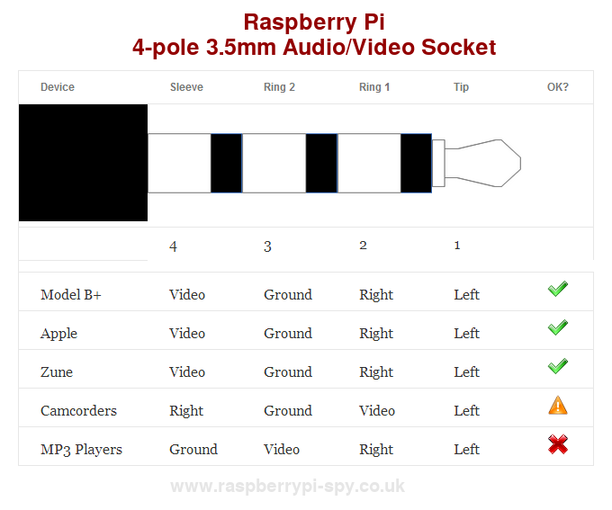
3 5mm Audio Video Wiring Diagram Wiring Schematic Diagram 70
Bantam Jack Wiring Diagram Wiring Diagram Data Schema
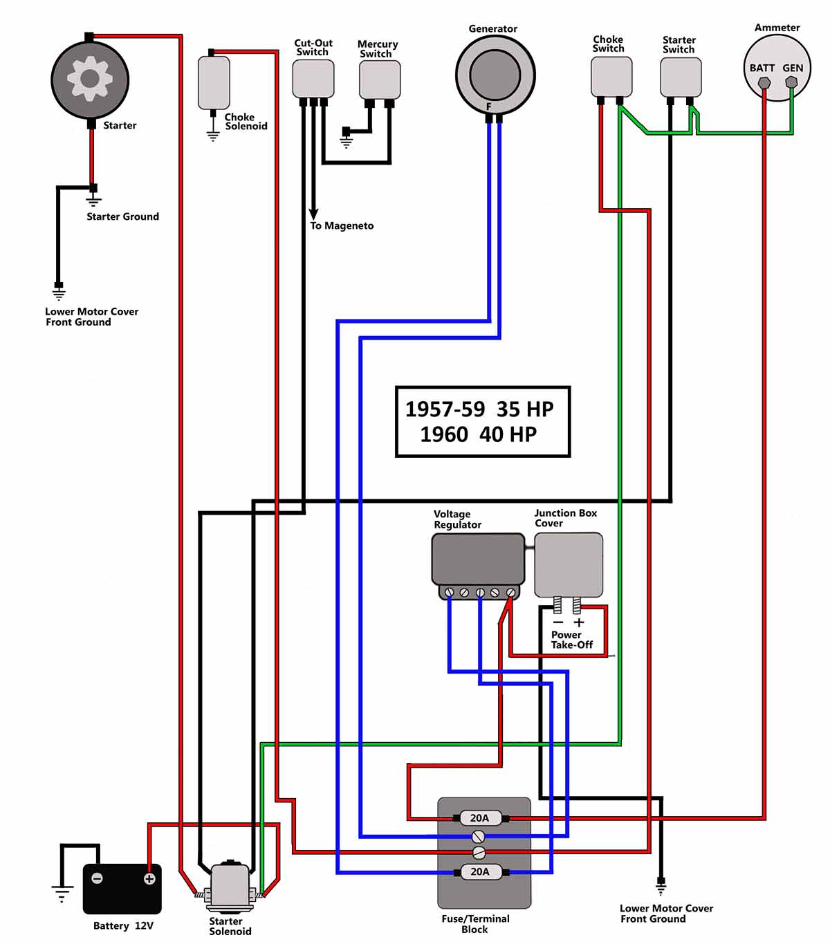
Evinrude Motor Switch Wiring Diagram Wiring Diagram Data Schema

Wire Headphone Jack Wiring Diagram On 2 Channel Amplifier Wiring

Headset Wire Diagram 7 Wiring Diagram Data Schema

Trs Cable Wiring Diagram Online Wiring Diagram
Pump Up Float Switch Wiring Diagram Dual Online Wiring Diagram
Trs Connector Wiring Diagram Online Wiring Diagram

Audio Jack Wiring Online Wiring Diagram

Headphone Jack Wiring Wiring Diagram Data Schema
Stereo Headphone Wiring Colors Diagram Data Schema

Valve Wiring Diagrams Online Wiring Diagram

3 5mm Audio Wiring Wiring Schematic Diagram 123 Beamsys Co

Headset Microphone Wiring Diagram Online Wiring Diagram

Rj48 Wiring Diagram Wiring Diagram Data Schema