Hvac body chime lock fuel pump fuel pair bag turn ignition power window blower motor wiperwasher cruise control dimpark lamp sunroof flasher radio rear defogger ump daytime running lamp. By karim nice the wiring.

Sakar Optical Usb Mouse Wiring Diagram Wiring Diagram Data Schema
Wiring diagram 3 pin flasher relay refrence fresh wiring diagram.
Flasher wiring schematic.
In this schematic you can see the system of anti theft flasher and also relay location inside your trucks wiring system.
Lets start with the first.
Rl44 spst relay.
1996 saturn twin cam engine fuse box diagram 1996 saturn twin cam engine fuse box map fuse panel layout diagram parts.
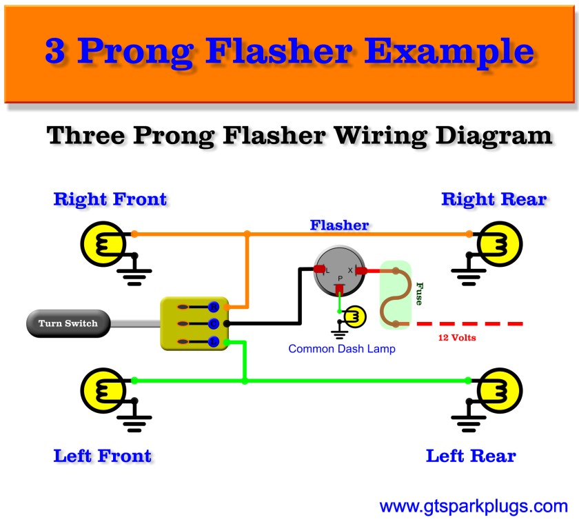
What you will need is a toggle switch and a flasher unit.
Wiring in turn signals that have their own seperate rear bulbs.
The turn signal circuit gets power when the ignition key is on.
Wiring in turn signals that share the rear bulbs with the brake and tail lights.
How turn signals work.
B x 49 battery power input c2 hazard switch ground e 31 ground h hazard switch i ignition l 49a load p pilot lamp s sense.
The switch connected both rear lights to the flasher and simultaneously connected a relay to the flasher.
Wiring diagram for turn signal flasher wiring diagram collection.
3 pin led flasher relay wiring diagram collections of 12v led flasher circuit diagram best 2 pin flasher relay wiring.
The relay in turn powered both left and right front indicators from a separate fuse source.
Led relay wiring diagram refrence wiring diagram 3 pin flasher relay.
The initial testing can be simply done using a 12 volt power supply and series automobile bulbs.
3 pin electronic led flasher.
The whole unit of this 12 volt flasher unit may be easily constructed with the help of the circuit schematic over a small piece of general pcb and can be finished within half an hour.
The power goes through a fuse panel into the thermal flasher.
They look something like this.
For the toggle switch you will need a spdt single pole dual throw toggle switch.
Flasher unit wiring diagram 2 pin mk2 mgbs used a rectangular 2 pin indicator flasher unit sfb115 was v8s have the same part number listed but shown as 2 pin in the diagram and the same any electrical circuit will lose some voltage in wiring and connections.
The following image is the anti theft system and relay location schematic diagram for the 1979 gmc light duty truck series 10 35.
Lets take a look at how the turn signal circuit is hooked up.
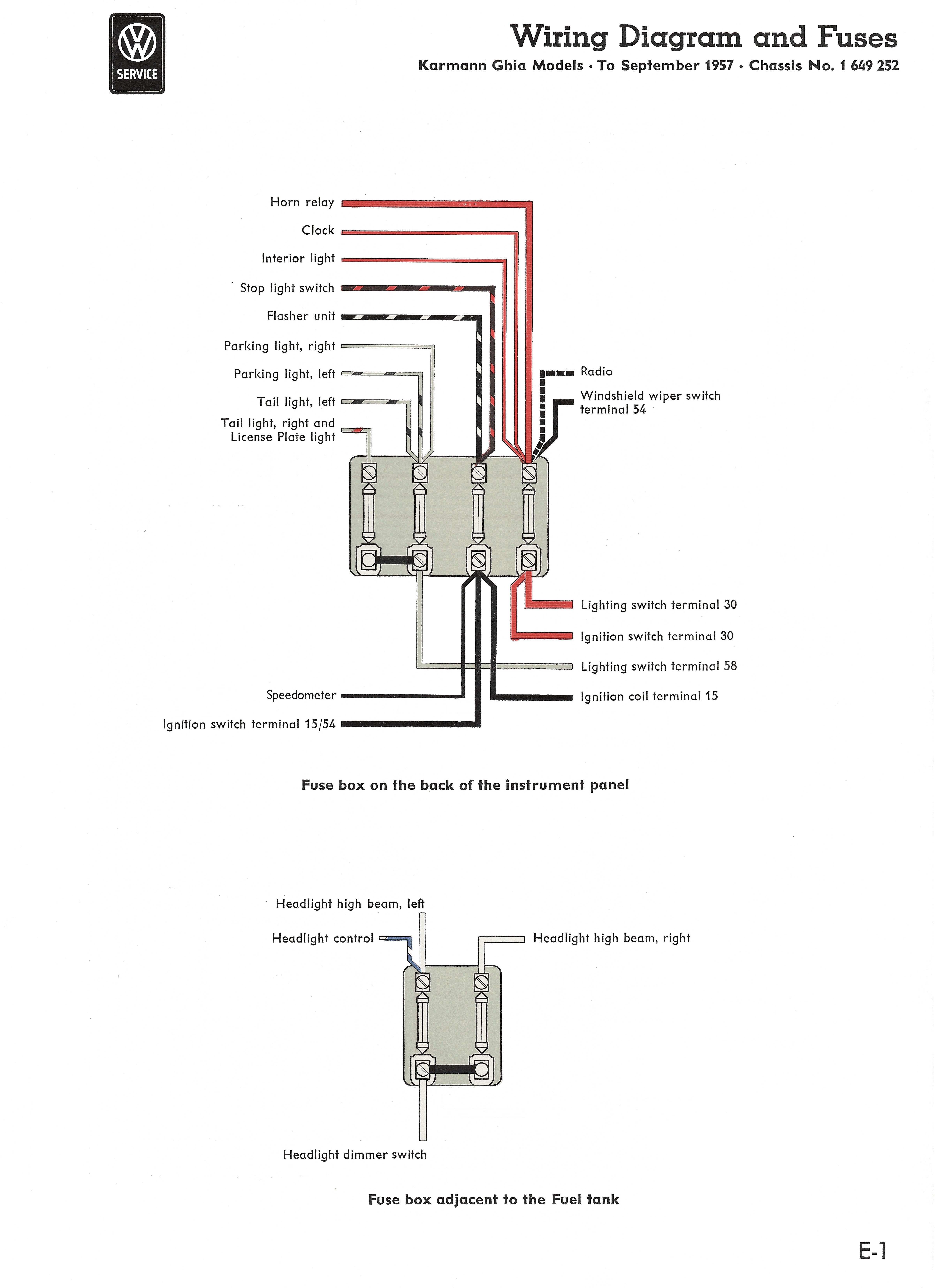
Early bus hazard wiring 62 thru 65 models used a switch and a relay to provide 4 way flashing hazard lights.
Led wig wag wiring diagram wiring schematic diagram thumb 77 cherokee wiring diagram auto electrical wiring diagram 2000 jeep cherokee sport wiring diagram i have 1996 s10 flasher wiring diagram wiring diagram library 1996 gmc wiring diagram 1996 chevy blazer turn graphic.

Signal Flasher Schematic Wiring Diagram

Honda Legend Wiring Diagram Electrical System Troubleshooting
Wiring Diagram Flasher Relay Diagram Data Schema

Klipsch Wiring Diagrams Wiring Diagram Data Schema

5 Blade Relay Wiring Diagram Wiring Diagram Document Guide

Automotive Flashers Gtsparkplugs
Automotive Flashers Gtsparkplugs
Component Led Light Circuits Blinking Bi Color

Led Emergency Flasher Wiring Schematic Flasher Wiring Diagram 12v

2012 Honda Goldwing Wiring Diagram Online Wiring Diagram

Ford Steering Column Wiring Schematic Wiring Diagram Data Schema

5 Blade Flasher Wiring Diagram Wiring Diagram Tutorial
Vw Light Switch Wiring Wiring Diagram Data Schema

Esp8266 Reflash Dance Xess Corp

2003 Yamaha Warrior Wiring Diagrams Online Wiring Diagram