Steps to take when wiring the electrical outletreceptacle. Here 3 wire cable is run from a double pole circuit breaker providing an independent 120 volts to two sets of multiple outlets.

Ac Receptacle Wiring Online Wiring Diagram
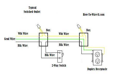
Electrical wiring for a switch outlet combination.

Electrical outlet wiring diagram.
This wiring is commonly used in a 20 amp kitchen circuit where two appliance feeds are needed such as for a refrigerator and a microwave in the same location.
Taking on this job by yourself rather than calling in an electrician will save you money and will help you build your confidence for doing additional homeowner electrical repairs.
This is how to rough in electrical wiring yourself.
Instead use wire connectors to connect the neutral hot and ground wires along with 6 in long pigtails then connect the pigtails to the outlet.
The following house electrical wiring diagrams will show almost all the kinds of electrical wiring connections that serve the functions you need at a variety of outlet light and switch boxes.
The neutral wire from the circuit is shared by both sets.
The slots are different sizes to accept polarized plugs but it lacks a grounding slot.
Wiring and installing an electrical outlet is an easy do it yourself project.
Wiring diagram for dual outlets.
With smartdraw you can create more than 70 different types of diagrams charts and visuals.
Wiring an ungrounded polarized outlet.
How to install an electrical outlet loop wiring example duration.
This is an older version of the receptacle outlet in the first diagram.
Wiring connections in switch outlet and light boxes.
How to install electrical outlet and switch combo wiring in most cases the primary power source is shared between the switch and the outlet either with a wire jumper or the bridge or tab that is located on the side of the combo switch and outlet.
House electrical wiring diagrams.
A wiring diagram is a simple visual representation of the physical connections and physical layout of an electrical system or circuit.
And second its easier to press the outlet back into the box if fewer of its screws are connected to wires.
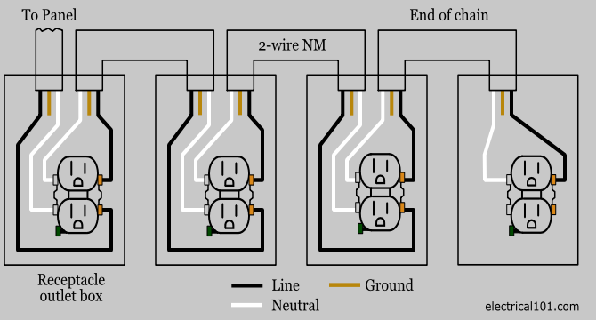
How to wire an electrical outlet wiring diagram wiring an electrical outlet receptacle is quite an easy jobif you are fixing more than one outlet the wiring can be done in parallel or in series.
This outlet does not make use of a ground wire and there is no protection against electrocution as provide by the grounded receptacle.
A basic explanation of the wiring of an electrical receptacle plug in so youll know what to do when replacing one.
It shows how the electrical wires are interconnected and can also show.
In the diagram below a 2 wire nm cable supplies line voltage from the electrical panel to the first receptacle outlet boxthe black wire line and white neutral connect to the receptacle terminals and another 2 wire nm that travels to the next receptacle.
More about wiring a switched outlet.
Outlet Wiring Electrical 101

How To Install Electrical Outlets In The Kitchen

Gfi Outlet Box Including Wiring Diagram For Gfi Outlet Diagram
Combination Switch Receptacle Wiring Diagram For Light And Switch

Home Wiring Diagrams Switch Outlet Online Wiring Diagram
Wiring Diagram Moreover Nest Thermostat Wiring Diagram On Wiring
House Electrical Wiring Connection Diagrams
Wire An Outlet

311 Fascinating Home Electrical Wiring Images Electrical Outlets

Basic Electrical Wiring Diagrams For Switches Wiring Diagram Data
Wiring Diagrams For Electrical Receptacle Outlets Do It Yourself

Outlet Light Switch Wiring Diagrams As Well Path Lighting Circuit

Electric Wiring Diagram Online Wiring Diagram

12 Volt Electrical Wiring Diagrams Symbols Online Wiring Diagram

1000 Ideas About Electrical Wiring Diagram On Pinterest Wiring