These lines far exceed the 120 volts ac standard in most homes. Contactor breakers limit switch no static control standard elementary diagram symbols.

Forward Reverse Motor Control Diagram With Timer Pdf Diagram
In addition to the simplicity which they offer in project engineering panel.

Contactor wiring diagram with timer pdf.
4 table 2 nema and iec terminal markings.
Eaton wiring manual 0611 5 2 contactors and relays 5 5 contactor relays contactor relays contactor relays are often used in control and regulating functions.
On delay timer circuit diagram wiring diagram contactor with push button circuit diagram of delay timer on off power off delay timer circuit diagram 2 way lighting circuit triggering transformer push button fan switch light activated switch circuit diagram wd081 text.
This relay is normally used in a dual bus configuration to tie both busses together in the case of an alternator.
Pdf contactor wiring diagram with timer.
M a1 a2 m.
How to wire a contactor.
Each component should be placed and linked to other parts in particular manner.
Wiring diagram book square d 8501 type nr socketswell guard pump panelsdefinite purpose contactors 8910square d nema relay.
Contactor wiring diagram contactor wiring diagram contactor wiring diagram 3 phase contactor wiring diagram ac unit every electrical arrangement consists of various distinct components.
Electronic motor starters and drives drives engineering basic information eaton wiring manual 0611 2 4 2 2 the rotation direction of a motor is always determined by directly looking at the drive shaft of the motor from the drive end.
They are used in large quantities for the indirect control of motors valves clutches and heating equipment.
On motors with two shaft ends the driving end is denoted with d drive the non driving end with n no.
The load and start the timing.
The diagram symbols in table 1 are used by square d and where applicable conform to nema national electrical manufacturers a ssociation.
240 volts ac and 480 volts ac are commonly used for these large pieces of.
Low input va permits long wire runs.
Cross tie contactor aka x tie contactor bus tie contactor is a continuous duty relay meaning it can be turned on indefinitely.
Many large pieces of equipment are powered directly from high voltage lines.
Otherwise the arrangement wont function as it.

Delta Motor Wiring Diagram Wiring Diagram

Photocell Wiring Diagram Pdf Diagram Data Schema

Dol Starter Control Wiring Diagram With Timer Pdf Popular

Timer Switch Wiring Diagram Pdf Basic Electronics Wiring Diagram

Contactor Wiring With Timer Wiring Diagram Third Level

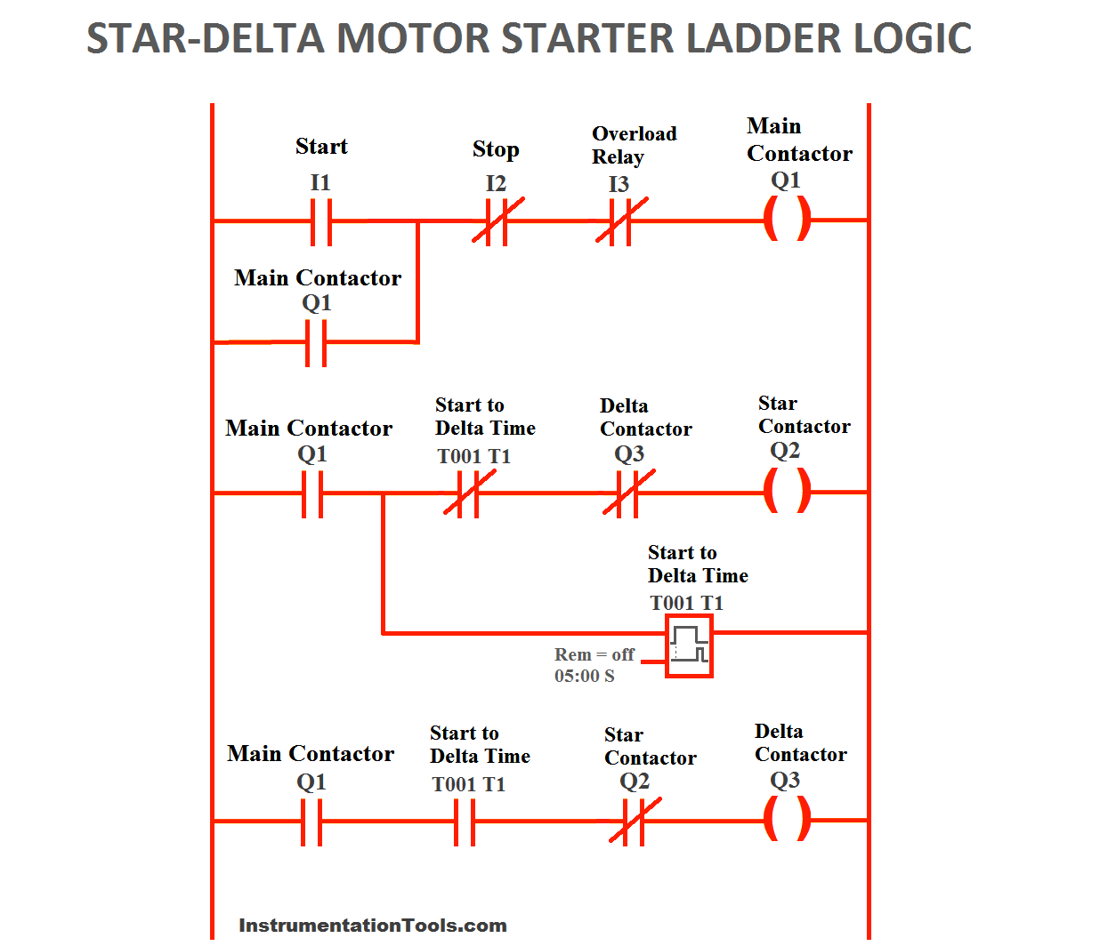
Star Delta Wiring Diagram With Timer Pdf Along With 3 Phase Star

Contactor Wiring Diagram With Timer Basic Electronics Wiring Diagram

Control Circuit Diagram Of Dol Starter Pdf Auto Electrical Wiring

Contactor Wiring Diagram With Timer Pdf Archives Servisi Co New

Cutler Hammer Wiring Diagrams 3 Phase Contactor Wiring Diagram Start

Contactor Wiring A Switch Of Online Wiring Diagram

Motor Control Diagram With Timer Fresh Time Delay Electromechanical

Https Www Airspringsoftware Com 1969 12 31t18 00 00 00 00 Hourly

Epo Wiring Diagram Contactor Technical Wiring Diagram

Contactor Wiring Pdf Basic Electronics Wiring Diagram