The engine operates contact breaker points which interrupt the. The colour coding however is a useful guide to tracing wiring.

System Of A Car Ignition Electrical Diagram Online Wiring Diagram
Wiring diagrams are also available for the entire wiring system of fords and chevys and other foreign and american made cars.

Car ignition system wiring diagram.
It must do this at exactly the right instant and do it at the rate of up to several thousand times per minute for each cylinder in the engine.
The most common component is the spark plug.
Automotive wiring diagram resistor to coil connect to distributor wiring diagram for ignition coil.
See how the anti.
1car starter wiring diagram non relay control type.
The purpose of the ignition system is to generate a very high voltage from the cars 12 volt battery and to send this to each sparkplug in turn igniting the fuel air mixture in the engines combustion chambers.
An ignition switch wiring diagram provides the schematics that are needed to enable auto owners to fix any wiring repairs related to their ignition system.
The purpose of the ignition system is to create a spark that will ignite the fuel air mixture in the cylinder of an engine.
The ignition system consists of an ignition coil distributor distributor cap rotor plug wires and spark plugs.
Learn to navigate this systems wiring circuitry and diagram using current flow analysis relay and module operation and neutral switch actuation such as circuit completion.
External to the distributor is the ignition coil the spark plugs and wires linking the distributor to the spark plugs and ignition coil.
There is no national or international system of colour coding.
Typical distributor style ignition system components.
To avoid confusion each wire is colour coded but only within the car.
Single starter relay car starter wiring diagram.
A car engines ignition system with distributor type ignition systems can seem complex but once simplified can be diagnosed with ease.
This ignition takes place thanks to a group of components working together otherwise known as the ignition system.
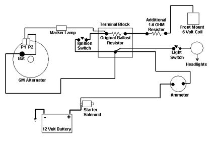
In mini cars equipped with small power starter the ignition switch start position is used to control the starter solenoid switch directly as shown in the picture below.
A complex network of wires runs through the car.
Wiring diagram for ignition coil more information find this pin and more on 63 f100 wiring by ben platt.
See diagram below the system is powered by a lead acid battery which is charged by the cars electrical system using a dynamo or alternator.
Older systems used a points and condenser system in the distributor newer as in most well ever see anymore use.
Using the diagram provided above you can see there are several different components.
Most car handbooks and service manuals include a wiring diagram which can be difficult to follow.
A short course on ignition systems.

Wiring Diagram Tractor Ignition Switch Online Wiring Diagram

Msd 8360 Wiring Diagram Wiring Diagram

92 325i Engine Harness Diagram Wiring Diagram Data Schema

Brp Evinrude Ignition Switch Wiring Diagram Boat Online Wiring Diagram

1999 Chrysler Lhs Ignition Wiring Diagram Online Wiring Diagram

Auto Solenoid Wiring Diagram Online Wiring Diagram

Gas Club Car Carry All Wiring Diagram Online Wiring Diagram

Car Ignition Wire Diagram Online Wiring Diagram

49cc Scooter Ignition Wiring Diagram Online Wiring Diagram

American Wiring Diagram Wiring Diagram

1966 Vw Coil Wire Diagram Wiring Diagram Data Schema

Bmw Ignition Control Module Wiring Harness Wiring Diagram Data Schema
Wiring Diagram Of Ignition System Wiring Diagram
Ford 2000 Tractor Wiring Diagram 6 Volt System Online Wiring Diagram

Ford F150 Wiring Diagram 1997 Online Wiring Diagram