Sometimes wiring diagram may also refer to the architectural wiring program. Wiring the resistor in parallel which is the only way your calculation makes sense is a huge waste of power and actually increases the load on your electrical system over stock incandescent bulbs which is really dumb and lazy.

Dodge Electronic Ignition Wiring Diagram Basic Electronics Wiring
Im assuming they mean a ballast resistor.

Ballast resistor wiring diagram.
Variety of 2 lamp t8 ballast wiring diagram.
It shows the components of the circuit as streamlined shapes as well as the power and also signal connections between the gadgets.
Ignition coil ballast resistor wiring diagram welcome to my internet site this blog post will certainly discuss concerning ignition coil ballast resistor wiring diagram.
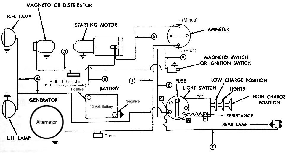
Electronic ignition conversion instructions simplified ignition charging diagram wdual ballast resistor electronic ignition simplified charging diagram wdual field alternator electronic.
Of course this meant that there was going to be a little less power getting to the coil.
If the leds cant function with the resistor in series then they are poorly designed and made and you shouldnt be.
A resistor that has the property of increasing in resistance as current flowing through it increases and decreasing in resistance as current decreases.
Mopar wiring electrical.
The typical automotive ignition system prior to 1974 consisted of a coil and ballast resistor with breaker points to interrupt the current flow when a spark was needed.
A wiring diagram is a streamlined standard pictorial representation of an electric circuit.
Technical chevy ignition question ballast resistor or not.
The wiring diagram on the opposite hand is particularly beneficial to an outside electrician.
This article is the first from the basic electronics.
It has some wires that are melted and a new wire harness is in the plans ahead.
Determine if ballast resistor is needed.
In many of todays vehicles the ballast resistor is not needed.
The simplest approach to read a home wiring diagram is to begin at the source or the major power supply.
The job of the ballast resistor was to inhibit current to a level that would not overheat the coil.
A ballast resistor is a resistor inserted into a circuit to compensate for different changes.
How do i wire a ballast resistor coil.
I dont know if it has a primary resistance wire.
We have gathered lots of images ideally this photo is useful for you as well as aid you in locating the response you are looking for.
I have looked up wiring diagrams online and havent seen any with a ballast resistor on the diagram.
Connecting a ballast resistor is a fairly straightforward project but you will want to pay attention to the wiring.
By tracy underwood.
Others might give a different answer to the question what is a ballast resistor like this.

Wiring Ballast Diagram Shelectrik Com

1959 Ford F100 Ballast Resistor Wiring Diagram
Yesterday S Tractors Converting To 12 Volt One Wire Alternator

I Have A 1986 F350 With A 460 Engine The Wiring From The Starter

12 Volt Ignition Coil Wiring Diagram Admirable Ignition Coil Ballast
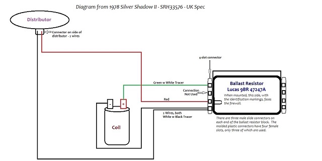
Australian Rr Forums Ballast Resistors Through The Years

Idea Ford Ballast Resistor Wiring Diagram For Full Size Of Ignition

Ballast Resistor Wiring Diagram Pertronix Delete Wiring Diagram
Chrysler Ignition Wiring Diagram L Fundacaoaristidesdesousamendes Com

Mopar Electronic Ignition Wiring Diagram Ballast Resistor Wiring

Inspirational Of Ignition Coil Distributor Wiring Diagram Gm Dr35

Mopar Ballast Resistor Wiring Diagram Wiring Diagram Online

Ford Blower Motor Resistor Wiring Diagram Replacing Circuit With

Chevy 350 Ignition Coil Wiring Diagram Ballast Resistor Fascinating

Ignition Coil Ballast Resistor Wiring Diagram Wiring Diagram