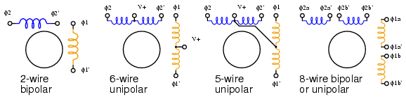
The two coils of the stepper motor are connected to a1 a2 and b1 b2 see below. Stepper motor is a type of brushless dc motor that converts electrical pulses into distinct mechanical movements ie.
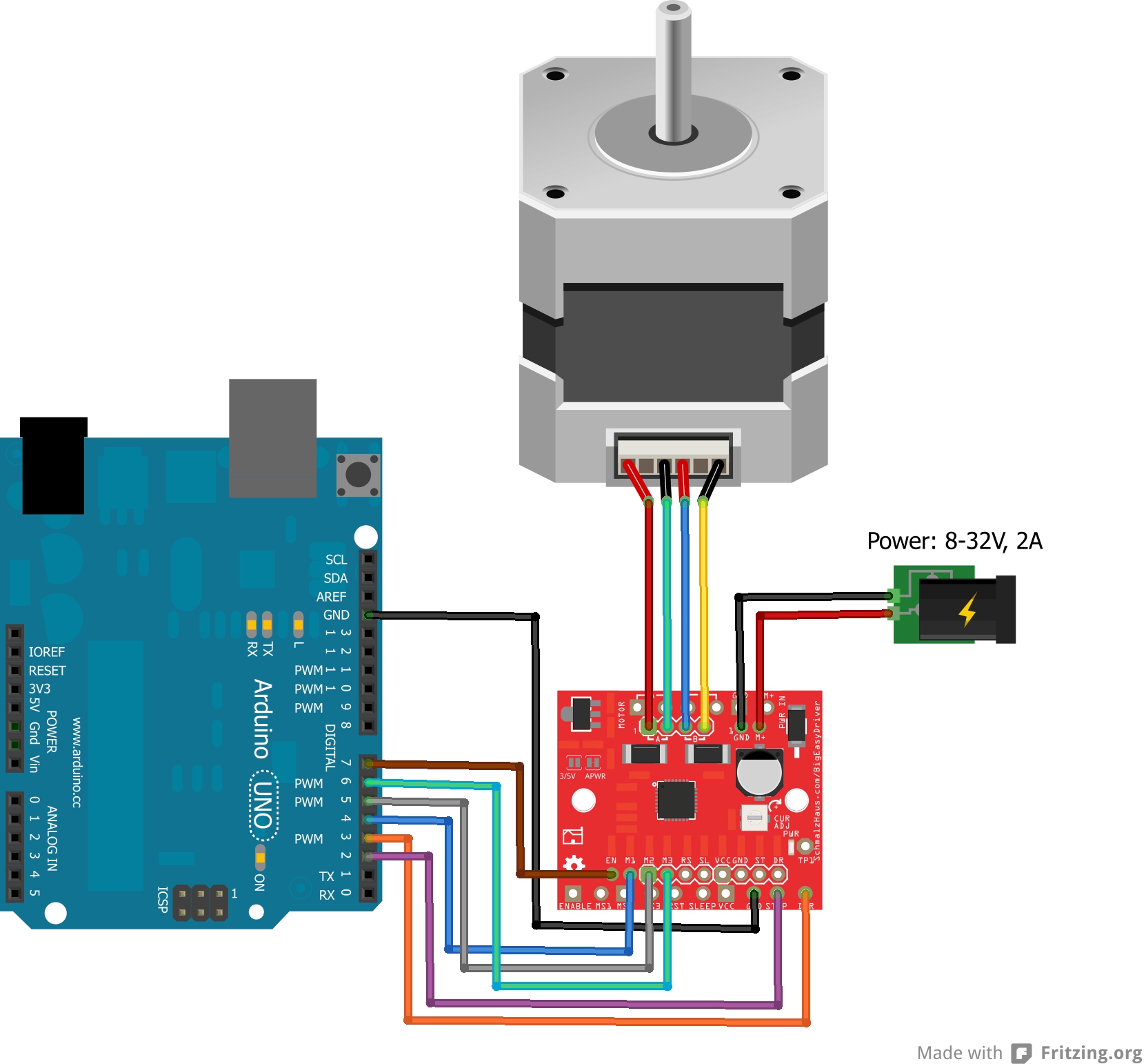
Big Easy Driver Hookup Guide Learn Sparkfun Com
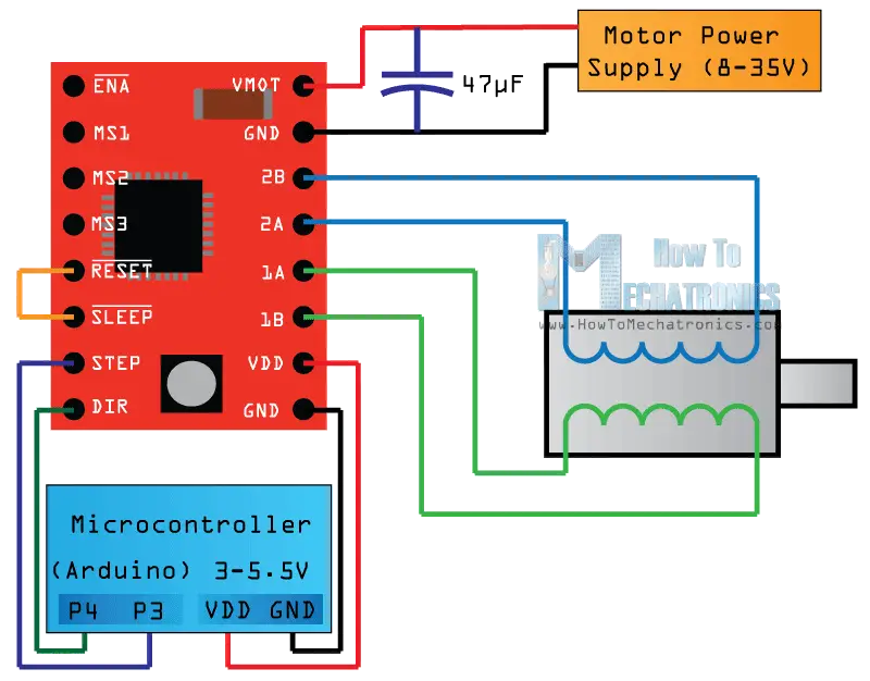
The wiring diagramschematic above shows you how to connect the drv8825 driver to a stepper motor and the arduino.
Arduino stepper motor wiring diagram.
L203d is a monolithic integrated that.
I have included a wiring diagram a tutorial on how to set the current limit and many example codes.
Your page is incredibly straight forward and useful congratulations and thank you i am trying to set up a bench lathe to work with mach3 and steppers but did not got a wire connecting diagram from the manufacturer sanyo denki even with the model type serial numbers.
This tutorial will show you how to operate a stepper motor that was salvaged from an old printer with an arduino.
Controlling a stepper motor with an arduino.
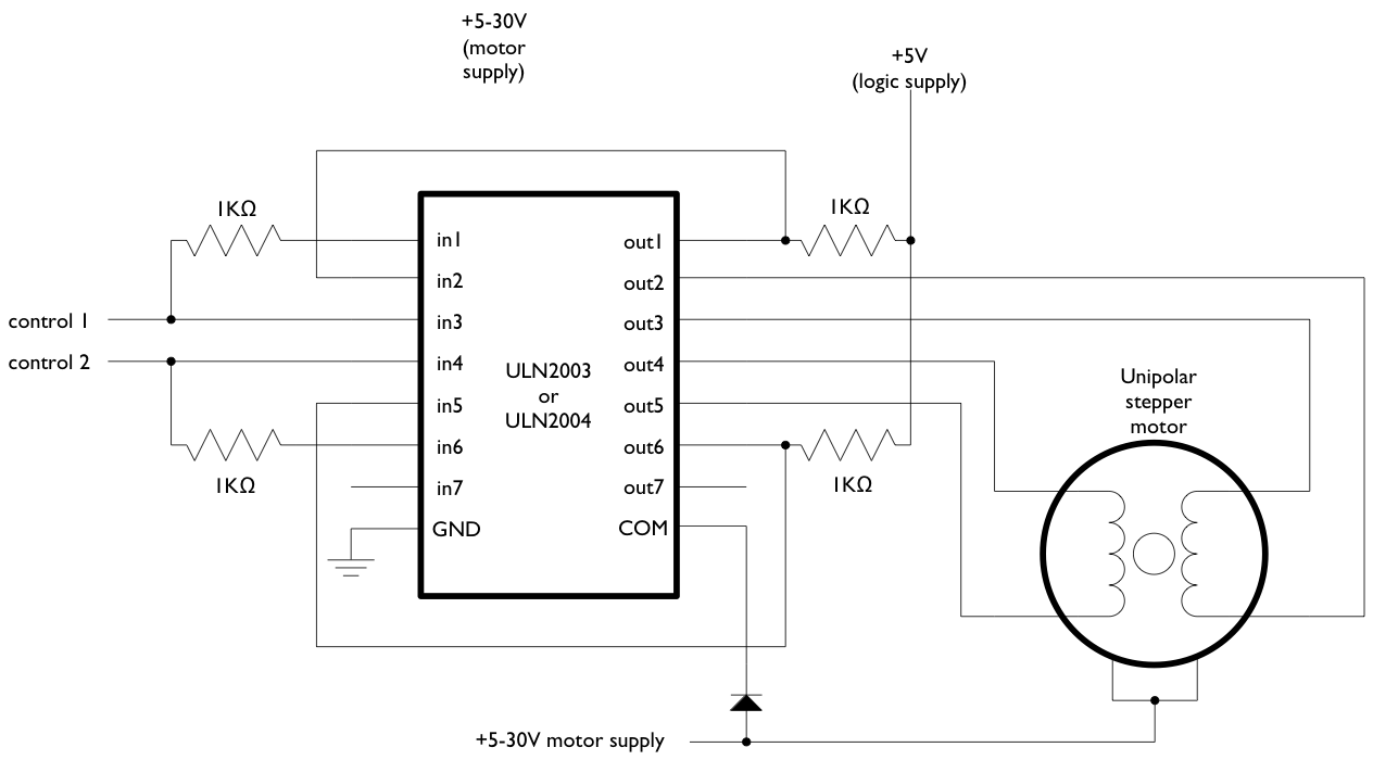
This library allows you to control unipolar or bipolar stepper motors.
The l293d is a dedicated module to fit in arduino uno r3 board and arduino mega it is actually a motor driver shield that has full featured arduino shield can be used to drive 2 to 6 dc motor and 4 wire stepper motor and it has 2 set of pins to drive a servo.
Arduino stepper motor control circuit diagram and explanation.
The gnd pin lower right is connected to the ground pin of the microcontroller.
Most stepper motors have four leads so you will need to cut four pieces of copper wire note the color does not correlate to anything specific.
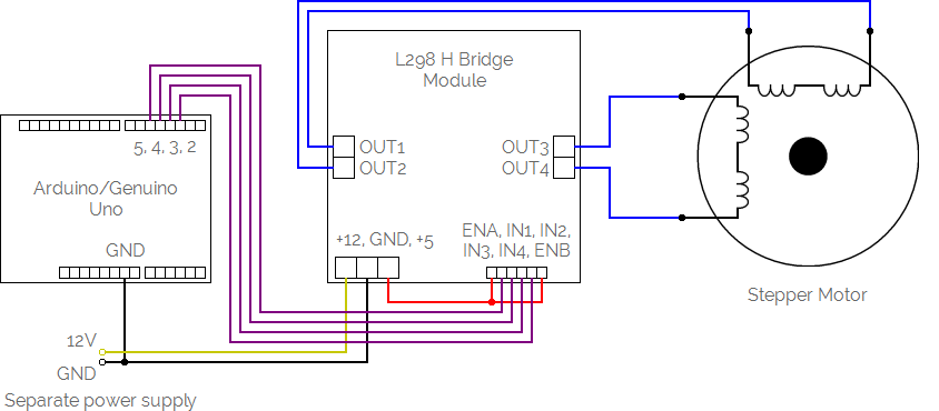
Stepper motor control using arduino is a simple project where a bipolar stepper motor is controlled using arduino uno.
This was an old stepper motor that i pulled out my junk pile im not sure what it came from i think it was an old printer from the 80s.
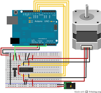
The circuit diagram for the arduino stepper motor control project is shown above.
7 thoughts on stepper motor wiring tutorial marcelo cabello november 24 2015.
The text of the arduino reference is licensed under a creative commons attribution.
The motor power supply is connected to gnd and vmot top right.
To energise the four coils of the stepper motor we are using the digital pins 8910 and 11.
To use it you will need a stepper motor and the appropriate hardware to control it.
The shaft of a stepper motor rotates in discrete steps.
This article includes everything you need to know about controlling a stepper motor with the a4988 stepper motor driver and arduino.
Arduino 6 wire stepper motor tutorial.
Arduino stepper motor tutorialhow to use an old six wire stepper motor and control it with an arduino.
The 4 logic pins will then connect.
For more on that see tom igoes notes on steppers.
We have used the 28byj 48 stepper motor and the uln2003 driver module.

Stepper Motor Control With Potentiometer Mert Arduino
Rulms3 Linistepper Driver Kit New V3 Massmind

L293d Circuit Diagram Fabulous Stepper Motor Circuit Automation
Arduino Stepperspeedcontrol
Stepper Motors Meccontrol

51 Amazing Models Of Stepper Motor Wiring Diagram Diagram With Labels

M35sp 7t Stepper Motor

Maxresdefault At Arduino Stepper Motor Wiring Diagram Ujjawal Me
Arduino Stepperunipolarcircuit
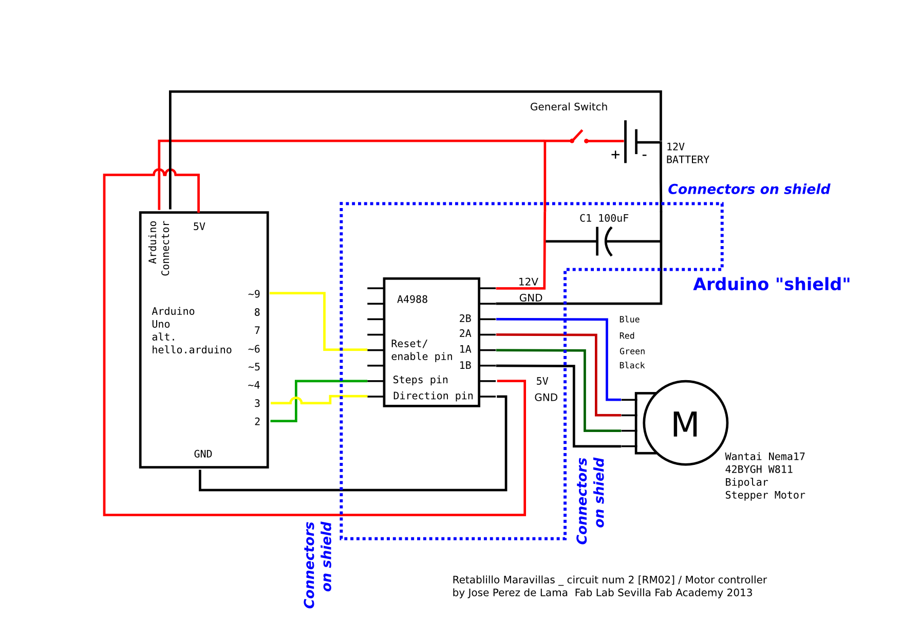
Fab Academy 2013 Fab Lab Sevilla Final Project Electronics
Arduino Unipolar Stepper Motor Control

Arduino Stepper Motor Control Circuit Diagram Arduino In 2019
How To Control Stepper Motor With A4988 Driver And Arduino
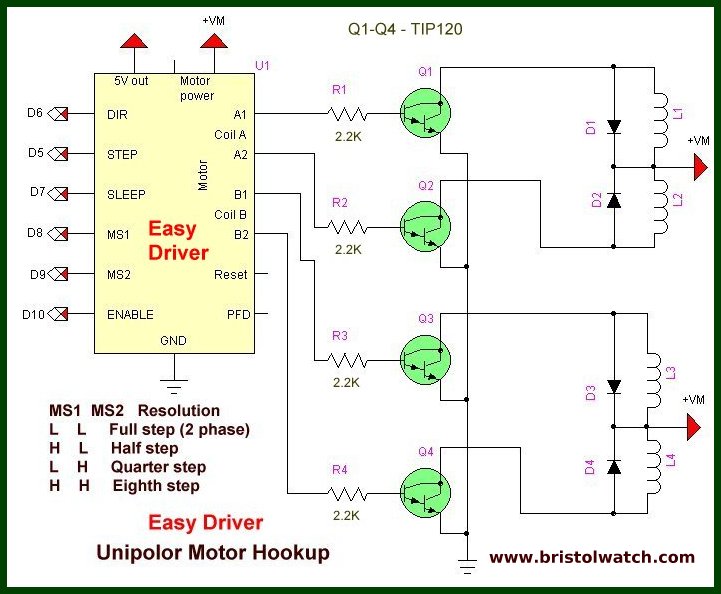
Arduino Connecting Easy Driver Stepper Motor Controller
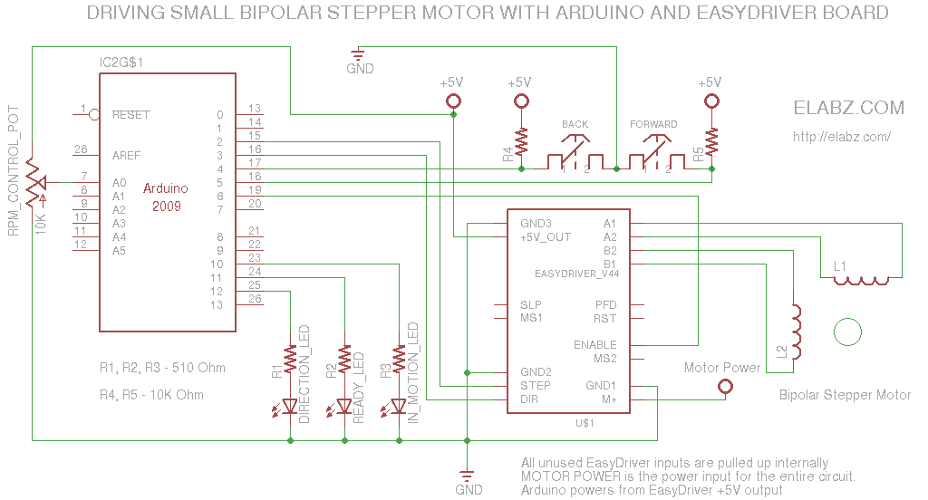
Manually Controlling Bipolar Stepper Motor With Arduino And Easydriver