Basically i have an lcd for which the back light is coming on but i am not getting any words appearing. Many lcds have this you can usually tell by the 16 pin interface.

Simple Graph With Arduino Nano And Tft Library Arduining
D0 d7 are the pins that have the raw data we send to the display.
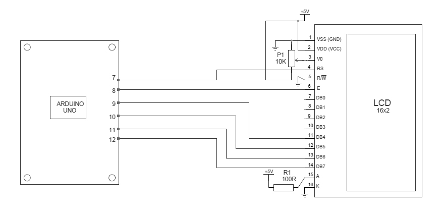
Arduino lcd display wiring diagram.
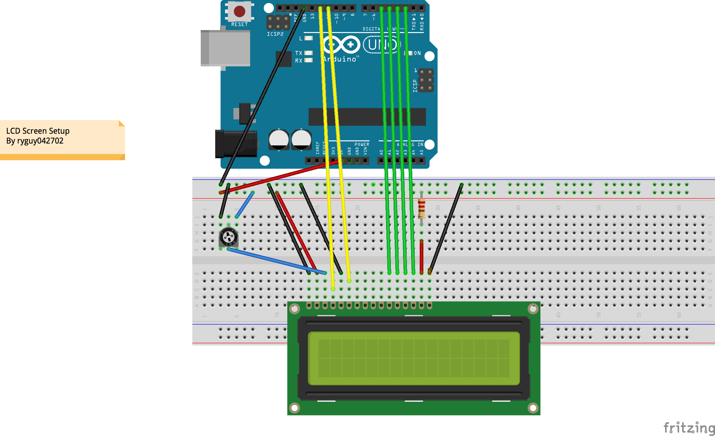
Alternatively a 5k potentiometer can be used to adjust the contrast for vest viewing.
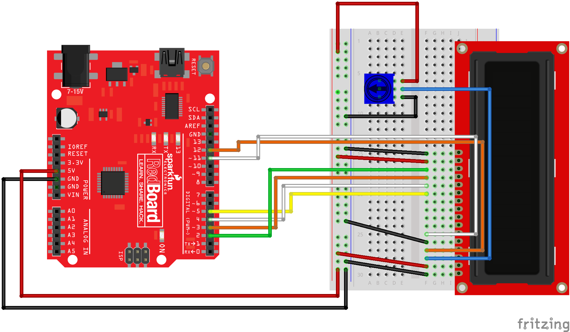
Lcd rs pin to digital pin 12 lcd enable pin to digital pin 11 lcd d4 pin to digital pin 5.
Youll of course need an arduino and the lcd display.
Lcd rs pin to digital pin 12 lcd enable pin to digital pin 11 lcd d4 pin to digital pin 5.
You can easily interface a liquid crystal display lcd with an arduino to provide a user interface.
Thers pin lets the microcontroller tell the lcd whether it wants to display that data as in an ascii character or whether it is a command byte like change posistion of the cursor.
That we need to figure out the hardware wiring which display pins go to which arduino pins.
This display module has only 096 diagonal made of 12864 oled pixels this module it works without backlight can be visible in the dark environment oled display is higher compared to lcd display.
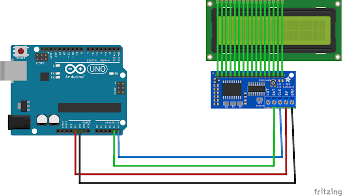
To wire your lcd screen to your board connect the following pins.
Has anyone got a really clear diagram of the way to link up a 16×2 lcd screen to an arduino.
Before wiring the lcd screen to your arduino or genuino board we suggest to solder a pin header strip to the 14 or 16 pin count connector of the lcd screen as you can see in the image above.
Getting the arduino lcd display wiring project together relies on just a few simple parts.
In this instructable well be looking at how to connect a parallel lcd to an arduino.
Before wiring the lcd screen to your arduino or genuino board we suggest to solder a pin header strip to the 14 or 16 pin count connector of the lcd screen as you can see in the image above.
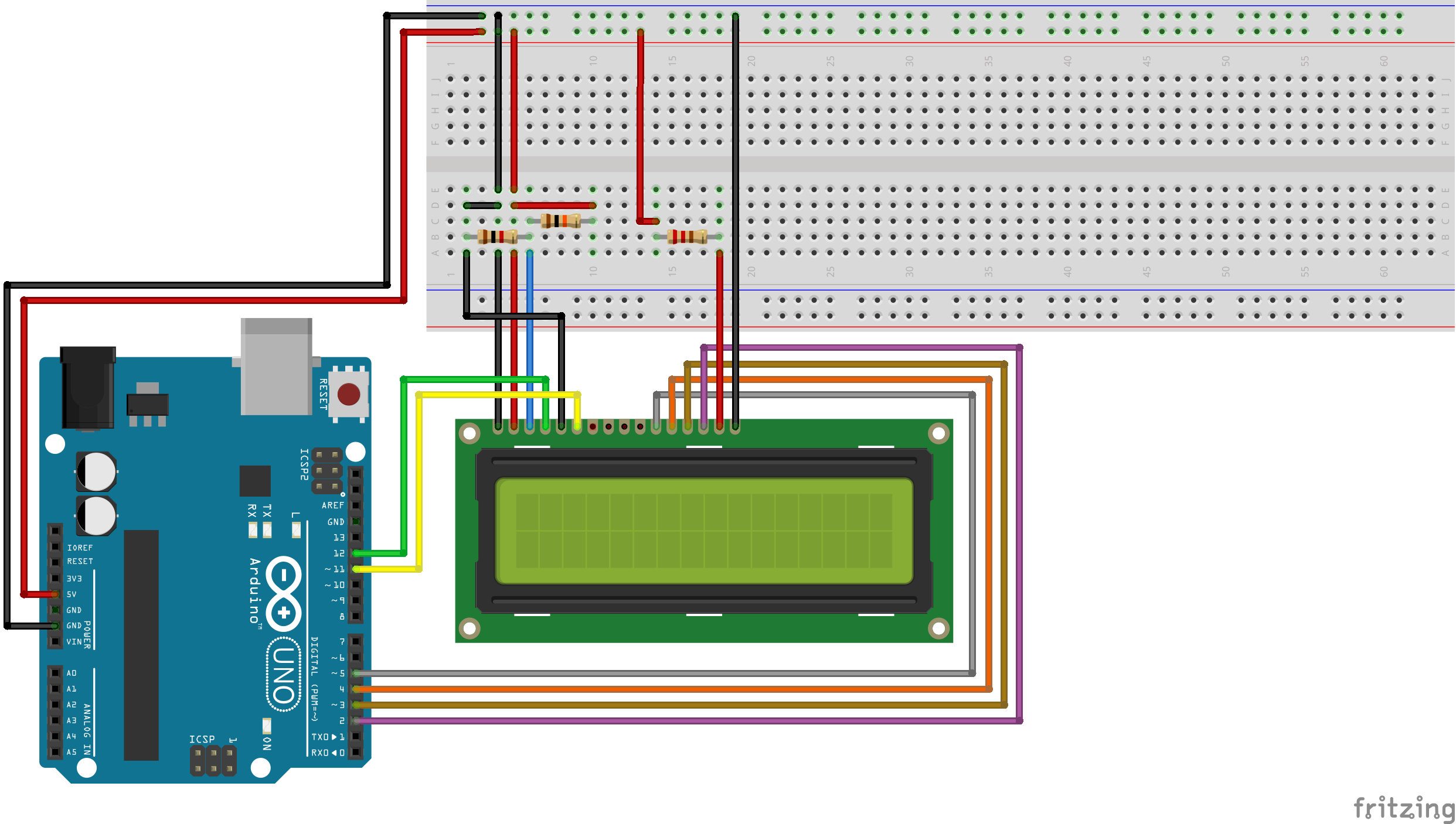
The table below explains how to connect the lcd pins to the arduino.
Arduino lcd display wiring basics.
Liquid crystal displays lcds are a commonly used to display data in devices such as calculators microwave ovens and many other electronic devices.
Connecting an lcd to the arduino.
As you can see the diagram below we used the pin 5 to pin 8 in arduino microcontroller to wire our oled display screen.
Youll also need a breadboard some breadboard wires and 10k potentiometer pretty close will do in a pinch.
The lcd that i am using uses the common hd44780 interface.
That an arduino can drive many commonly available cheap tft lcd displays.
In this tutorial i will show you how to use a.
That we need to identify the display family and the library containing the necessary drivers.
In the case where the lcd is powered with the arduino by the 5v usb cable selecting the contrast resistor to be 2k ohm and the back led resistor to be 100 ohm is a good start.
You only need to solder 10 of th.
To wire your lcd screen to your board connect the following pins.

Serial Lcd Kit Quickstart Guide Sparkfun Electronics

In Depth Tutorial To Interface 16×2 Character Lcd Module With Arduino

How To Integrate A Temperature Sensor Circuit To An Lcd
Using A Jhd162a Lcd Screen With An Arduino Uno Rastating Github Io

How To Set Up An Lcd With Arduino Programming Electronics Academy

Interface An Lcd With An Arduino
Text On Your Display Arduino Project Hub
Fritzing Project Lcd Screen Setup Tutorial
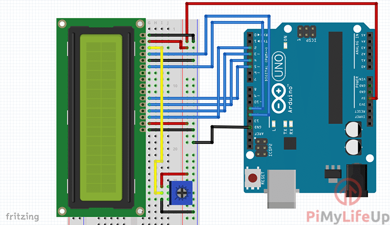
Arduino Lcd Using A 16×2 Liquid Crystal Display Pi My Life Up
Sik Experiment Guide For Arduino V3 2 Learn Sparkfun Com

16×2 Lcd Interfacing With Arduino Uno Circuit Diagram And C Code
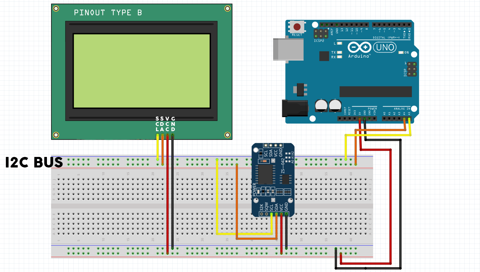
Real Time Clock On 20×4 I2c Lcd Display With Arduino Electronics Lab
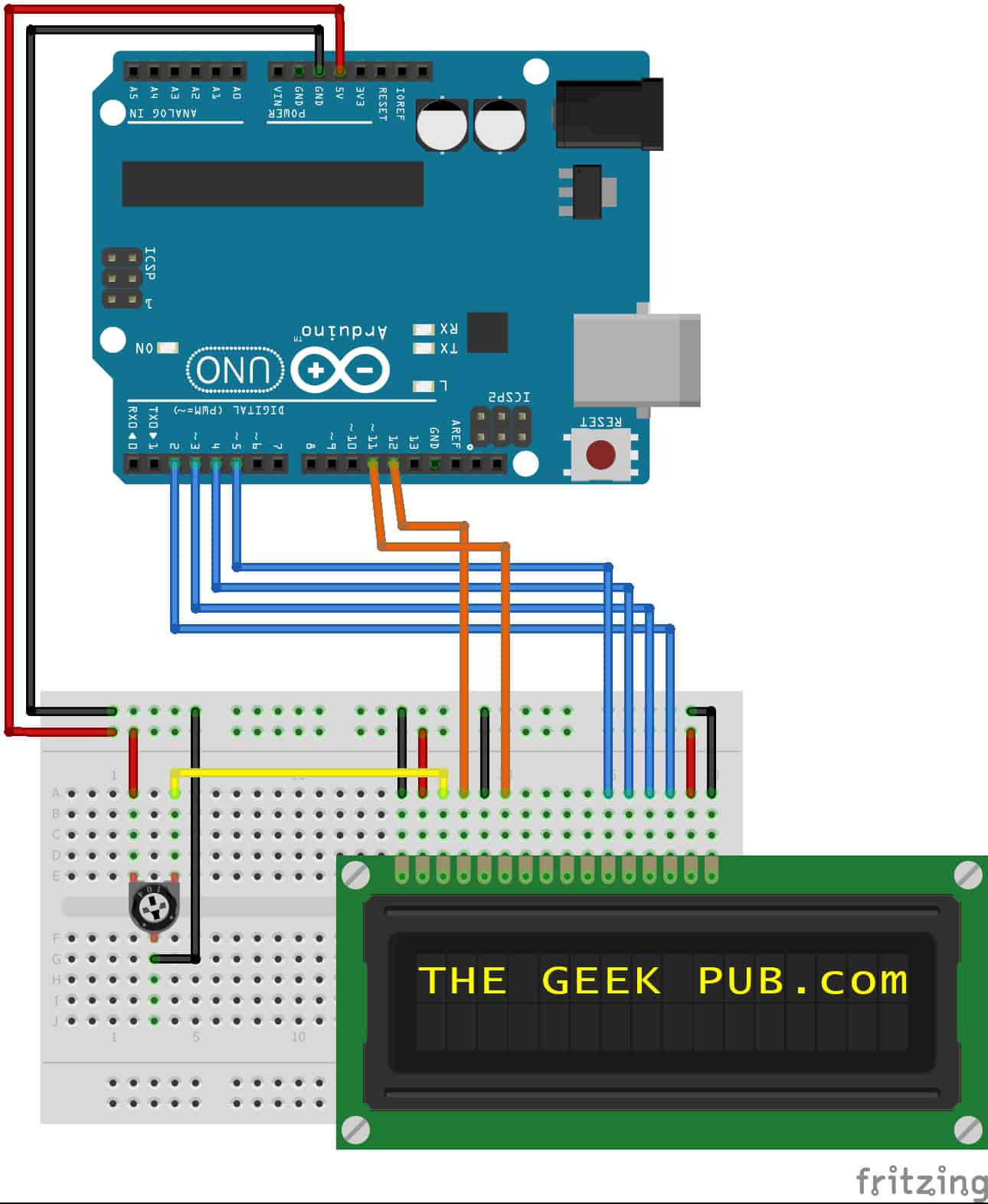
Arduino Lcd Display Wiring The Geek Pub

Arduino Based Digital Temperature Sensor Arduino Project Hub
Arduino Ds1307 Clock