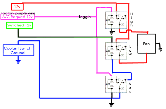
A wiring diagram is a simplified traditional pictorial representation of an electrical circuit. Straight cool air conditioning condensing unit.

Ruud Contactor Wiring Diagram Basic Electronics Wiring Diagram
If not the arrangement will not work as it should be.

Ac contactor wiring diagram.
Collection of ac contactor wiring diagram.
The heat source for a basic ac system can include heat strips for electric heat or even a hot water coil inside the air handler that is fed from a water heater.
How to wire a contactor.
A wiring diagram is a simplified standard pictorial depiction of an electric circuit.
These lines far exceed the 120 volts ac standard in most homes.
Wiring an outdoor condenser.
Each part should be placed and connected with other parts in particular manner.
This book contains examples of control circuits motor starting switches and wiring diagrams for ac manual starters drum switches starters contactors relays limit switches and.
And where the low voltage powering the contactor is coming from.
What each of the wires is for how it works.
Ac contactor wiring diagram 3 phase ac contactor wiring diagram ac condenser contactor wiring diagram ac contactor wiring diagram every electric structure consists of various diverse parts.
Visit our website to learn more about fixing your own air conditioning unit read articles and wiring manuals along with all the parts you need.
This document is current but may reference obsolete products.
How to wire an air conditioner for control 5 wires the diagram below includes the typical control wiring for a conventional central air conditioning systemit includes a thermostat a condenser and an air handler with a heat source.
240 volts ac and 480 volts ac are commonly used for these large pieces of.
Collection of contactor wiring diagram ac unit.
It reveals the elements of the circuit as streamlined forms and the power and also signal links between the gadgets.
Overload relays ac motors dc motors wiring capacitors resistors semiconductors table 1 standard elementary diagram symbols contd iron core air core auto iron core air core current dual voltage thermal magnetic single phase 3 phase squirrel cage 2 phase 4 wire wound rotor armature shunt field show 4 loops series field show 3 loops.
It shows the elements of the circuit as simplified forms and the power and also signal connections between the tools.
Many large pieces of equipment are powered directly from high voltage lines.
A simple circuit diagram either of the two start buttons will close the contactor either of the stop buttons will open the contactornote that one one of the contactor acts as a switch for the start button.
All power must be shut off before.

Air Conditioners Wiring Diagram Online Wiring Diagram

Ac Contactor Wiring Diagram Online Wiring Diagram

Realay Ac Fan Wiring Wiring Diagram Tutorial

Single Phase Wiring Diagram Online Wiring Diagram

Compressor Control Wiring Diagram Wiring Diagram Data Schema

Wiring Contactors Diagram Basic Electronics Wiring Diagram

Ac Contactor Wiring Diagram Basic Electronics Wiring Diagram

Pump Contactor Wiring Diagram Wiring Diagram

110 Ac Fan Wiring Wiring Schematic Diagram 54 Beamsys Co

Single Phase Reversing Motor Contactor With Wiring Diagrams Wiring

Heat Pump Contactor Wiring Diagram Online Wiring Diagram

Ac Wiring Diagram Single Phase Motor To Control 3 Online Wiring

Central Ac Compressor Wiring Diagram Carrier Air Conditioner

Ev Ac Motor Wiring Diagram Wiring Diagram Data Schema

Razor Electric Scooter Wiring Diagram Also Contactor Relay Wiring