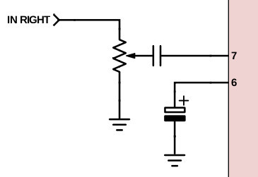
Refer to diagram 6 below for a graphical representation. Sometimes youll see a potentiometer in a circuit diagram connected like this.

Push Pull Pots How They Work Wiring Mods And More
Potentiometers more commonly known simply as pots are a type of electrical component called a variable resistor.

4 wire potentiometer wiring diagram.
We will share this website for you articles and images of wiring diagrams engine schemes engine problems engine diagrams transmission diagrams.
How to wire 4 pin potentiometer.
Back to understanding guitar wiring index.
Easily control motor speed with a knob.
A wide variety of 4 wire potentiometer options are available to you such as optical sensor resistance sensor and current sensor.
They usually function in conjunction with a knob.
Nigel goodwin.
The user turns the knob and this.
At some point in an electronics project you might find yourself needing a variable resistor.
How to wire a potentiometer.
Connecting a potentiometer or analog joystick.
Simple motor controller can be directly connected to a 0 to 33 v analog voltage source such as a potentiometer or analog joystick allowing for simple manual motor control eg.
When the pot reaches full clockwise rotation10 on the knoba is now at 0 and b is still at 100.
4 wire potentiometer wiring diagram welcome thank you for visiting this simple website we are trying to improve this website the website is in the development stage support from you in any form really helps us we really appreciate that.
Thegoodnightshowus 4 wire trailer wiring diagram trailer wiring diagram for 4 way 5 way 6 way and 7 waytrailer wiring.
John 22nd april 2006 0724 pm.
Wire a potentiometer as a variable resistor.
4 pin potentiometers wiring together with 4 pin relay potentiometer how it works stirling engine pot leaf peace sign 4 pin led 4 pin connector potentiometer wiring american standard faucet cartridge 4 pin cable black 4 pin potentiometer 3 pin potentiometer 10k ohm potentiometer 4 pin potentiometer schematic wire terminals types 4 pin potentiometer pinout 4 pin plug wire potentiometer 5 pin.
I have the alps pot connected in manual mode as per this diagram.
Adjustable gain of an amplifier adjustable cutoff freque.
I have a dual gang pot with 4 pins on each channel how is this wired up.
Wiring diagram for connecting a potentiometer or.
The potentiometer and wiring guide.
The middle and bottom pin are connected.
Variable resistors are useful for the following.
The pot in the diagram has two unconnected pins just used for mounting the pot is yours like that.
3 way switch with pilot light fresh wiring diagram for trailer from 4 wire trailer wiring diagram source.
Keep that in mind and have a look at the following three examples on how to wire a potentiometer.
November 14 2018 march 8 2019 ideas by keith armstrong.
About 62 of these are sensors 9 are potentiometers.
4 wire potentiometer 4 wire trailer wiring diagram.
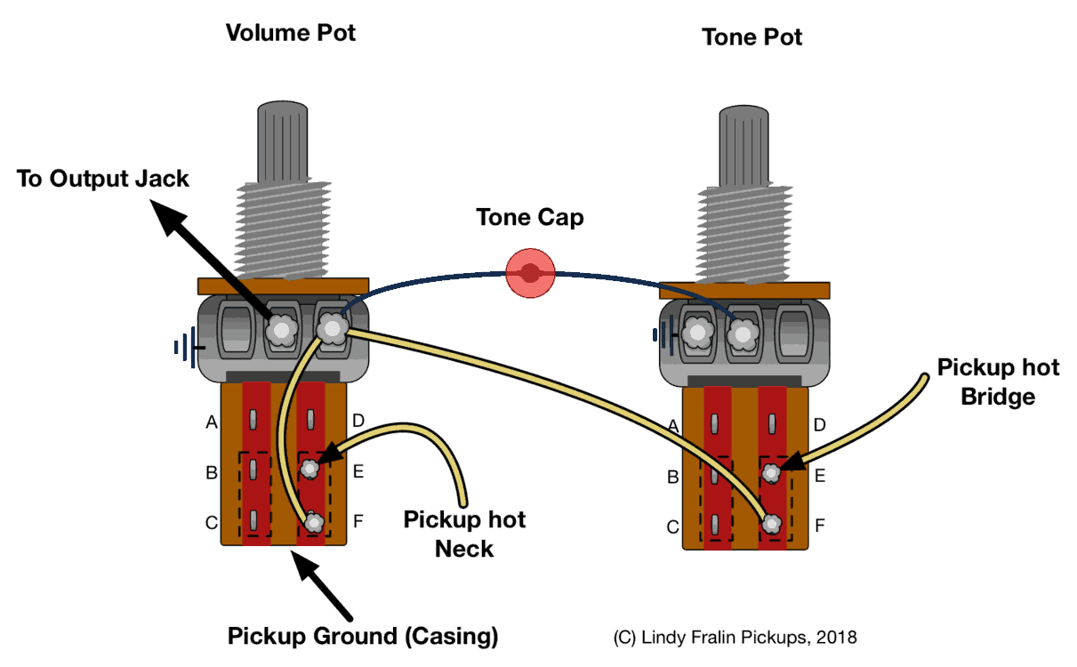
Since these are audio taper blend controls the taper is logarithmic.
Heres how to make one using a potentiometer.

Patent Us5864116 D C Chopper With Inductance Control For Drawing

Common Electric Guitar Wiring Diagrams Amplified Parts
The Potentiometer And Wiring Guide Build Electronic Circuits

Pololu 4 4 Connecting A Potentiometer Or Analog Joystick

Multiple Fluorescent Light Wiring Diagram Online Wiring Diagram

Latest 4 Wire Potentiometer Wiring Diagram Potentiometer Wiring

Box Mod Mos Fet Wiring Diagram Pot Wiring Diagram Data Schema
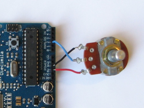
Arduino Potentiometer

Potentiometer Wiring Diagram Fan Circuit Diagram Template
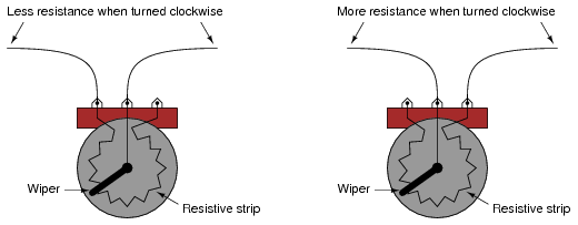
Potentiometer As A Rheostat Dc Circuits Electronics Textbook

How To Wire A Potentiometer 6 Steps With Pictures Wikihow

Wiring A Potentiometer Basic Electronics Wiring Diagram
Push Pull Pots How They Work Wiring Mods And More
The Potentiometer Internal Resistance Of A Test Cell

Potentiometer Wiring Audio Wiring Diagram