Polyphase motor generator page. 3 phase 6 lead motor wiring diagram elegant awesome 12 lead 3 phase.

3 Phase Motor Wiring Diagram Wiring Schematic Diagram 131 Beamsys Co
Patent and trademark office.

3 phase motor wiring diagram 12 leads.
3 phase motor wiring diagram 12 leads gallery how to check polarity of each winding in 3 phase motor.
3 phase motor wiring diagram 12 leads sample how to check polarity of each winding in 3 phase motor.
For example use a red wire nut to connect two 12 gauge wires.
I need wiring diagrams for 3 phase 240480v 12 lead 75 hp ac industrial motors.
Hold the bare ends of the conductors together and twist on a wire nut.
The 3 phase ac source line voltage l1 is connected to the motor terminals 1 12 line voltage l2 is connected to the motor.
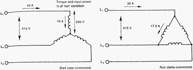
Typical connection diagrams three phase motors y start delta.
Connect motor leads 5 and 8 together.
How to wire a 3 phase motor by michael.
12 leads terminal wiring guide for dual voltage delta connected ac induction motor.
Typical connection diagrams three phase motors y start delta.
Nidec motor corporation trademarks followed by the symbol are registered with the us.
This is a 3 phase dual voltage motor.
Typical connection diagrams three phase motors y start delta.
Connect motor leads 6 and 9 together.
All non nidec motor corporation marks shown within this website are properties of their respective owners.
Typical connection diagrams three phase motors y start delta.
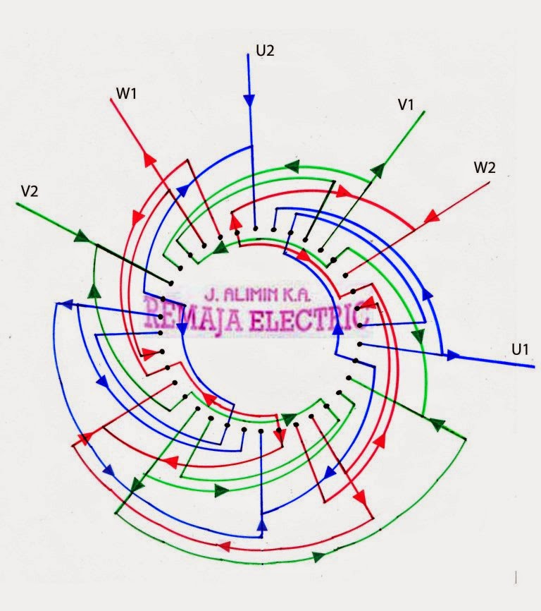
Electric motor wire marking connections.
The 12 leads represent six different windings.
Typical wiring diagrams always use wiring diagram supplied on motor nameplate connection diagrams co4 460 12 leads part winding weg three phase motors 460 volts 12 lead part winding 12 10 11 645 789 12 3 l1 l2 12 10 11 64 5 78 9 12 l1 l2 12 10 11 64 5 789 123 l1 l2 starting type 460 volts across line starting type 460 volts soft.
Three phase wiring diagrams always use wiring diagram supplied on motor nameplate colored leads are only applicable on the new rolled steel motor lines single phase wiring diagrams always use wiring diagram supplied on motor nameplate for motors with thermal protection single voltage single rotation single voltage reversible rotation.
For the higher voltage pairs of windings are connected in series then the three resulting pairs are.
Fig 1 above shows an electrical schematic diagram of a delta configured 12 leads motor so connected for a 440 volts ac power supply.
For specific leeson motor connections go to their website and input the leeson catalog in the review box you will find connection data dimensions name plate data etc.
Connect motor leads 4 and 7 together.
High and low volts need winding answered by a verified electrician.

Marathon Motors Wiring Diagram Online Wiring Diagram
Speed Control Methods Of Various Types Of Speed Control Motors

June 2014 Electrical Winding Wiring Diagrams

Phasor Diagram And Phasor Algebra Used In Ac Circuitsbasic

Wye Wiring Diagram Basic Electronics Wiring Diagram
Delta Motor Wiring Diagram Basic Electronics Wiring Diagram
Three Phase Motor Winding Diagram Luxury Three Phase Induction Motor

Phasor Diagram And Phasor Algebra Used In Ac Circuitsbasic

Dual Voltage 3 Phase Motor Wiring Diagram On 9 Wire 3 Phase Motor
2 Phase Wiring Diagram Online Wiring Diagram
100v 1 Phase Wiring Diagram Wiring Schematic Diagram 177 Beamsys Co

208v 3 Phase Motor Wire Diagrams For Wiring Diagram Data Schema
Delta Motor Wiring Diagram Basic Electronics Wiring Diagram

Motor Wiring Installation Tips Electrical Construction

Duvac Alternator Wiring Diagram Online Wiring Diagram