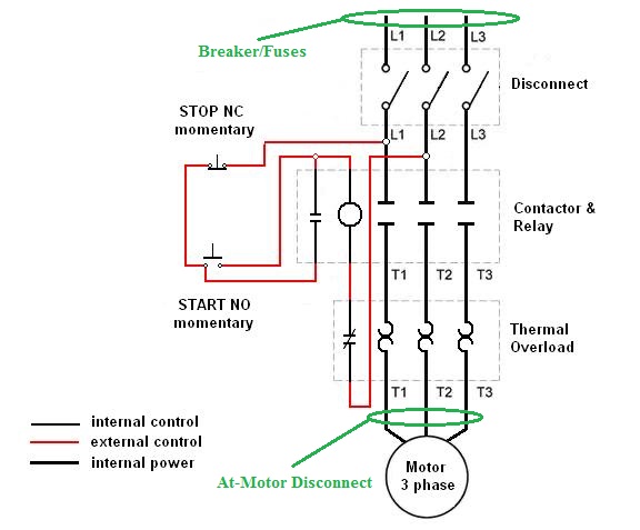
A double pole switch is the safest way to make sure that both lines of the 240 volt circuit power to the pump are turned off. 4 product ratings packard c340c 3 pole 40 amp contactor 208240 volt coil contactor 1849 trending at 2378 trending price is based on prices over last 90 days.

Motor Contactor Wiring Diagram Pressure Online Wiring Diagram
It reveals the elements of the circuit as streamlined shapes as well as the power and also signal connections in between the gadgets.

240 volt contactor wiring diagram.
A 120 volt circuit has only one hot wire connected to the breaker plus a neutral wire connected to the neutral bus bar in the service panel.
Each part should be set and connected with different parts in particular way.
How to wire a contactor.
240 volt contactor wiring diagram 220 volt contactor wiring diagram 240 volt coil contactor wiring diagram 240 volt contactor wiring diagram every electrical arrangement consists of various distinct pieces.
Assortment of 240 volt photocell wiring diagram.
A wiring diagram is a type of schematic which makes use of abstract photographic signs to show all the interconnections of parts in a system.
These lines far exceed the 120 volts ac standard in most homes.
How to wire a control switch for a 240 volt pump.
Many large pieces of equipment are powered directly from high voltage lines.
Icons that represent the components in the circuit and also lines.
Wiring a control switch for a 240 volt pump.
The contactor then uses the set of conductive discs the contacts to supply a 240 vac power source to something like an air conditioner unit or an air compressor.
If not the arrangement wont function as it ought to be.
There are several types of contactors that we sell.
In other words a 120 volt alternating current commonly referred to as a 120 vac is wired to the coil of the contactor.
240 volts ac and 480 volts ac are commonly used for these large pieces of.
2 pole contactor wiring diagram 6 inside 4 240 volt 5 natebird.
A wiring diagram is a streamlined standard pictorial depiction of an electrical circuit.
A 3 wire 240 volt circuit has two hot wireseach supplying 120 volts for a total of 240and an equipment ground wire.
When controlling a 240 volt motor it is best to install a double pole switch for this irrigation pump.
Wiring diagram book square d 8501 type nr socketswell guard pump panelsdefinite purpose contactors 8910square d nema relay.
The contactor has a 24 volt relay when this 24 volt relay is energized from the thermostat a call for cooling the contacts on the contactor close making a high voltage 220 240 connection to your compressor and outdoor fan causing the outdoor unit to come on.
Wiring diagrams are composed of 2 things.
Just whats wiring diagram.

2 Pole Contactor Wiring Diagram For In A1 A2 I Have A 240 Volt

240v Double Pole Switch Wiring Diagram Online Wiring Diagram

Combination Motor Controller Wiring Diagram Wiring Diagram Data Schema

Packard 2 Pole Contactor Wiring Diagram Online Wiring Diagram

110 220 Single Phase Motor Wiring Diagram Wiring Diagram Data Schema

3 Phase Contactor Wiring Diagram Wiring Schematic Diagram 54

3 Phase Contactor Wiring Diagram Wiring Diagram Document Guide

Control 240 Volt With Wemo

Single Phase Contactor Wiring Diagram Need To Wiring Library

240 Volt Relay Wiring Diagram Online Wiring Diagram

Ac Motor Relay Wiring Diagram Online Wiring Diagram

2 Phase Wiring Diagram Online Wiring Diagram

120 Volt Contactor Wiring Diagram Simple 220 To 110 Wiring Diagram

Led Light Bar Control Box Wiring Diagrams Wiring Diagram Data Schema

240 Volt Contactor Wiring Wiring Diagram Tutorial