Ladder diagram basics 4 multiple stop start stations duration. A wiring diagram is a simplified traditional pictorial depiction of an electric circuit.

Packard 2 Pole Contactor Wiring Diagram Online Wiring Diagram
I find millions of ladder diagrams but no diagrams of physically wiring the switch relay and motor.
Motor starter wiring diagram start stop.
Manual motor starters.
Typical wiring diagrams for push button control stations 7 start stop control wiring diagrams single station with motor stopped pilot light l1 start l2 i 1 stop 2 oi 3 n wol.
Stations are built using normally closed stop and normally open start momentary contact switches.
The term jogging is often used when referring to full voltage starting of loads.
This video explains the basics of a simple start stop motor control circuit.
These switches must be rated for the control circuit voltage at a minimum.
Can anyone help me find any diagrams of wiring the motor controls.
3 wire start stop circuit.
Starting a three phase motor.
Collection of motor starter wiring diagram start stop.
T w 6.
It shows the parts of the circuit as streamlined shapes and also the power and also signal connections between the devices.
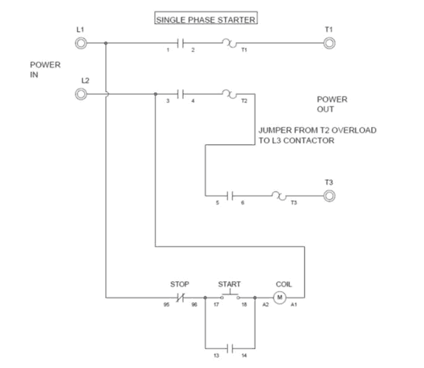
How to wire 3 phase magnetic starters or contactors for single phase use and.
Motor starter wiring diagram start stop what is a wiring diagram.
Basic startstop circuit.
Ladder diagram basics 3 2 wire 3 wire motor control.
A wiring diagram is an easy visual representation in the physical connections and physical layout associated with an electrical system or circuit.
The most common use of 3 wire control is a startstop control.
Motor starter schematic and wiring diagram.
Pilot light l2 4 2 3 pilot light start stop bulletin 1495 normally closed auxiliary contacts are required.
I cant find any diagrams on google or on the net.
Jogging or inching is dened as the quickly repeated closure of a circuit to start a motor from rest for the purpose of accomplishing small movements of rotating machine.
However motor starters are designed to trip on heater overload before the motor they start burns up.
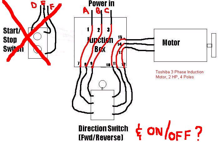
Im trying to understand the concept of physically wiring a startstop switch with a relay to control a motor.
It shows what sort of electrical wires are interconnected and will also show where fixtures and components could possibly be.
Start stop 3 wire control.
C i m nc.
The term inching can be used to refer to reduced voltage starters.
Motor starter wiring diagrams print.
See image below for an example of 3 wire control being used to pull in a contactor to start a 3 phase motor.

5 Wire Start Stop Diagram Wiring Schematic Diagram 108 Beamsys Co

Start Stop Motor Control Wiring Diagrams As Well Start Motor Control

Single Phase Reversing Motor Contactor With Wiring Diagrams Wiring

Venn Diagram Logic Engine Schematic Wiring Diagram Data Schema

3 Phase Motor Contactor Wiring Diagram Magnetic Circuit Best Start

Diagram Also Diagram 1 Phase Motor Starter Wiring Diagram Single

Cj5 Wiper Motor Wiring Diagram Online Wiring Diagram

1966 Mustang Starter Wiring Diagram Online Wiring Diagram

Three Phase Dol Starter Wiring Diagram Component Single Motor

Control Wiring 3 Wire Control Start Stop Circuit
Wiring A Single Phase Motor Through A 3 Phase Contactor How And Why
Contactor Relay Wiring Diagram Get Free Image About Wiring Diagram
Two Wire Three Wire Motor Control Circuit Motor Control Circuit

5 Wire Start Stop Diagram Wiring Schematic Diagram 108 Beamsys Co

1990 F250 Starter Solenoid Wiring Diagram Online Wiring Diagram