Installing a universal fuel sender from veethree elec marine llce nz and a mercury digital fuel gauge from trademe seller silverdalemarine on my boat. If the gauge then reads full scale then the problem was with your sender.

2004 Fleetwood Revolution Battery Wiring Diagram Online Wiring Diagram
Gauge and sending unit wiring diagram and industry recommendations.

Boat fuel gauge wiring diagram.
Locate the fuel sending unit.
Check the wiring diagram that comes with the kit and mark the back of the new fuel gauge with symbols for each post.
Gasoline is extremely flammable.
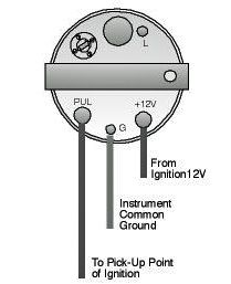
One wire comes from the ignition to the instrument one wire comes from the sensor to the instrument one wire comes to the instrument light and one wire from the instrument goes to the boats common ground.
Connect sender wire from fuel gauge to the threaded screw terminal on sender.
You may need a partner to complete this simple task depending upon how you proceed.
Connect a wire to the gauge stud marked s signal and secure with nut and lock washer.
If not unplug the pink wire and connect it to a known good ground like your engine block or the negative terminal on your battery.
This is often.
Here is a quick method of determining whether the fault lies in your boats fuel gauge or in the fuel gauge sending unit on the tank.
Connect hot wire to the i terminal and ground wire to g terminal.
Wiring a fuel gauge is much the same as wiring any other gauge on your boat.
The fuel gauge should now show the correct fuel level in.
Get a new one.
How to wire a marine fuel tank gauge by will charpentier.
Test gauge as follows.
Connect ground wire to 14 fasson terminal on sender.
Dangar marine 106828 views.
See diagram on the next page for connections standard case 3.
Empty tank of fuel and fumes before continuing with installation.
Boat fuel gauges can be troublesome.
Wiring the electrics on a boat pt 1 duration.
Install the new gauge reconnect the wiring and turn on the power.
How to wire fuel gauge and sending unit complete explanation duration.
Connect opposite end to the fuel level senders signal wire or terminal.
S for the sender g or for the ground and i for the ignition.
Fuel systems marine voltage i to g terminal 10 to 16 volts.
Wiring the electrics on a boat pt 1.
It is recommended that insulated wire terminals preferably ring type be used on all.
Keep tank area free from sparks and flames.
For the fuel gauge its best to remove it from the tank and manually work the float mechanism to see if the gauge then moves.
To test senders the resistance values are shown at minimum and full gauge scales.
Gauge pointer should be at the position shown in the lower portion of the diagram.

Boat Gauges Wiring Wiring Schematic Diagram 54 Beamsys Co

Wiring Diagram For Gauges Online Wiring Diagram

Th350c Diagram Http Wwwmontecarlosscom Community Ubbthreadsphp

Wiring Diagram 12 Volt Led Marine Flood Wiring Diagram Data Schema

Johnson Trim Gauge Wiring Diagram Online Wiring Diagram

Tack Wiring Diagram Online Wiring Diagram

Wiring Diagram On Wiring For Temp Oil Gauge Further Auto Meter Water

Vtx 1300 Gas Tank Wiring Diagram Online Wiring Diagram

Sending Unit Plug Wiring Diagram Online Wiring Diagram
Engine Instrument Wiring Made Easy Boats Com

Gas Gauge Wiring Diagram 85 Chevy Online Wiring Diagram
Gps Sensor Diagram Online Wiring Diagram

Fuel Gauge Diagram Wiring Diagram Document Guide

Contura Switch Dpdt Wiring Diagram Wiring Diagram Data Schema
Troubleshooting Teleflex Fuel Gauges