The low voltage will be 125 volts or less. Sometimes you apparently need to rewire a 3 phase motor for low voltage 230v as opposed to 460v in order to connect the motor to a vfd.

Rectification Of A Single Phase Supplybasic Electronics Tutorials
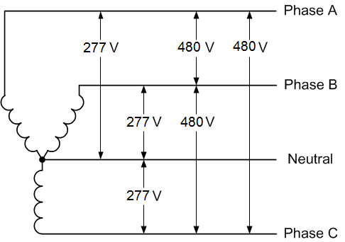
Just as you have three different phase to neutral readings you will have three different phase to phase readings.
3 phase low voltage wiring diagram.
These instructions cover a dual voltage three phase motor the most common type.
3 phase wire diagram daytonva150.
3 phase motor wiring diagram 9 leads perfect luxury 9 lead motor.
Three phase wiring diagrams.
It is a type of polyphase system and is the most common method used by electrical grids worldwide to transfer power.
The connection diagram on the left shows how a deltadelta connection can be made.
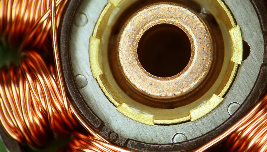
A three phase motor is more efficient than a single phase motor because of the peculiarities of alternating current ac.
It will specify two voltages one high and one low.
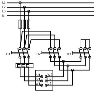
Wire a three phase motor in either a wye configuration or a delta configuration in high or low voltage using a nine lead set up.
The high voltage will be 200 volts or more.
When the transformer windings are drawn a particular high voltage winding corresponds to the low voltage winding.
Two wiring configurations wye and delta indicate the wiring methods for three phase motors.
There will also be a rollout switch a flue spill switch and such as this three phase motor controller.
Dayton electric motors wiring diagram gallery.
The voltage cycle of each line lags its predecessor by 120 degrees l2 reaches its peak voltage after l1 and l3 reaches its peak voltage after l2.
In the low voltage circuit the phase currents are identical to the corresponding line currents so they also are labeled i a i b and i c.
How to wire a single phase 230v motor by michael logan.
Low voltage power systems different wiring topologies.
There is no single 3 phase voltage that answers this question.
Three phase electric power is a common method of alternating current electric power generation transmission and distribution.
3 phase motor wiring diagram 9 leads collections of amazing baldor electric motor wiring diagram motors 10 3 wiring.
Supplied on motor nameplate colored leads are only applicable on the new rolled steel motor lines single phase wiring diagrams always use wiring diagram supplied on motor nameplate.
This apparently involves the windings and associated wire configuration.
It is also used to power large motors and other heavy loads.
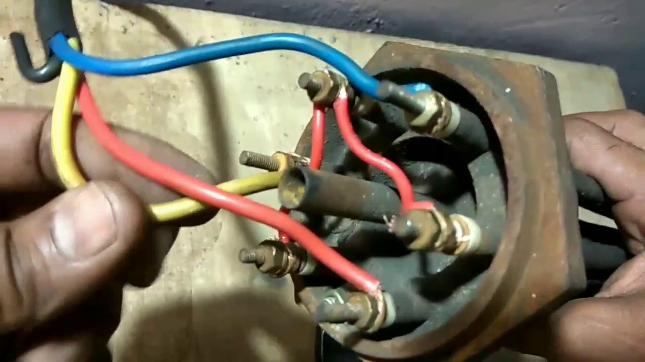
Look at the underside of the cover for the wiring diagram which specifies which wires are used to wire the.
3 phase low voltage motor wiring diagram i asked what the voltage was a high limit control a low water cutoff as a safety device and a thermostat setting the comfort level.
Dual voltage single rotation split phase motor dual voltage reversible rotation capacitor motor single phase wiring.
Automatic Transfer Switch Ats Between Two Low Voltage Utility Supplies
Induction Motor Starting Methods
Phase Heater Wiring Diagram On 480v 3 Phase Heater Wiring Diagram

Low Voltage Motor Wiring Diagram Wiring Diagram Document Guide
How To Wire A High Low Voltage Three Phase Motor Sciencing

Lead 3 Phase Motor Wiring Diagram On High Low Voltage 3 Phase Motor

3 Phase Induction Motor Connection Diagram Beautiful Delta Motor

3 Phase Dual Voltage Motor Wiring Schematic Single Phase Wiring
High Leg Delta Motor Wiring Wiring Diagram Data Schema

Circuit Diagram Of Variable Frequency Drive Download Scientific
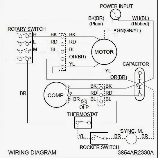
3 Phase Hvac Compressor Wiring Wiring Schematic Diagram 177

Baldor High Voltage And Low Voltage Wiring Wiring Diagram
Low Voltage Three Phase Wiring Diagram Online Wiring Diagram

240 Volt Motor Wiring Diagram 220 Electric A O Smith Ac Enthusiasts
How To Wire A High Low Voltage Three Phase Motor Sciencing