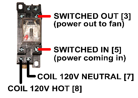
Relay internal wiring diagram new wiring diagram indoor blower motor. How to wire an air conditioner for control 5 wires the diagram below includes the typical control wiring for a conventional central air conditioning systemit includes a thermostat a condenser and an air handler with a heat source.

Sparkys Answers 2008 Chevrolet Cobalt Blower Inop Cobalt Blower
Hvac fan relay wiring diagram download.

Hvac fan relay wiring diagram.
Variety of hvac fan relay wiring diagram.
A wiring diagram is a simplified standard photographic depiction of an electrical circuit.
Suggested electric fan wiring diagrams page 1 these diagrams show the use of relays onoff sensors onoff switches and onoff fan controllers.
The heat source for a basic ac system can include heat strips for electric heat or even a hot water coil inside the air handler that is fed from a water heater.
It reveals the parts of the circuit as streamlined shapes and the power as well as signal connections between the devices.
A5 minute timer time delay relay tdr will prevent the compressors from restarting for 5 minutes after any com pressor has stopped.
Air handler fan relay wiring diagram collections of goodman air handler wiring diagram delightful model first thermostat.
Goodman furnace wiring diagram packet wiring diagram portal.
Plus fan relay hvac parts can be snatched up from ebay top rated sellers so you can shop without worries.
If you follow these steps you may.
Get more for less by scrolling through new manufacturer refurbished or barely used fan relay hvac parts.
A package unit the blower fan is in the outdoor package unit.
On a split system the blower fan is in the air handler.
If the condenser fan motor overheats due to motor over load or lack of cooling air the internal fan protector will open the circuit internally in the motor and the fan will stop.
G this is the terminal used for the fan relay to energize the indoor blower fan.
For the thermostat wiring colors code for this terminal if equipped consult with the installer or trace the wire out to the source.
Protects relay from arcing damage due to fan spinning.
Diagram showing a need for a 12 volt switched device.
Toward the fan or relay and away from ground.
Choose the appropriate size from the listings shown here to get exactly what you want.

8 Pin Relay Configuration Diagram Online Wiring Diagram
Furnace Fan Relay Wiring Diagram Wiring Diagram Document Guide

Hvacquick How To S Wiring Generic 120v Coil Relay From

Hvac Fan Relay Wiring Diagram For Thermostat To Boiler A C Heater

7 Best Images Of Electrical Diagram Symbols Wiring Wiring Diagram Read

Air Conditioning Relay Wiring Diagram Basic Electronics Wiring Diagram

Starter D Diagram Wiring Square Motor 8911dpsg32v09 Online Wiring

1989 Toyota Van Fuse Box Online Wiring Diagram

Csr Compressor Wiring Diagram Online Wiring Diagram

Fan Relay Wiring Diagram 12v Ac At Hvac Webtor Me Within With On

Electric Fan Relay Wiring Diagram Awesome Volvo Electric Cooling Fan

Atwood Ac Wiring Diagram Online Wiring Diagram

Hvac Hard Start Capacitor Wiring Diagrams Online Wiring Diagram

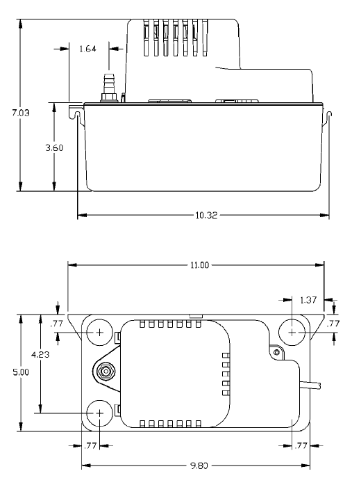
Condensation Pump Wiring Diagram With Fan Coil Unit Wiring Diagram

Fan Relay Wiring Diagram F250 Wiring Diagram Data Schema