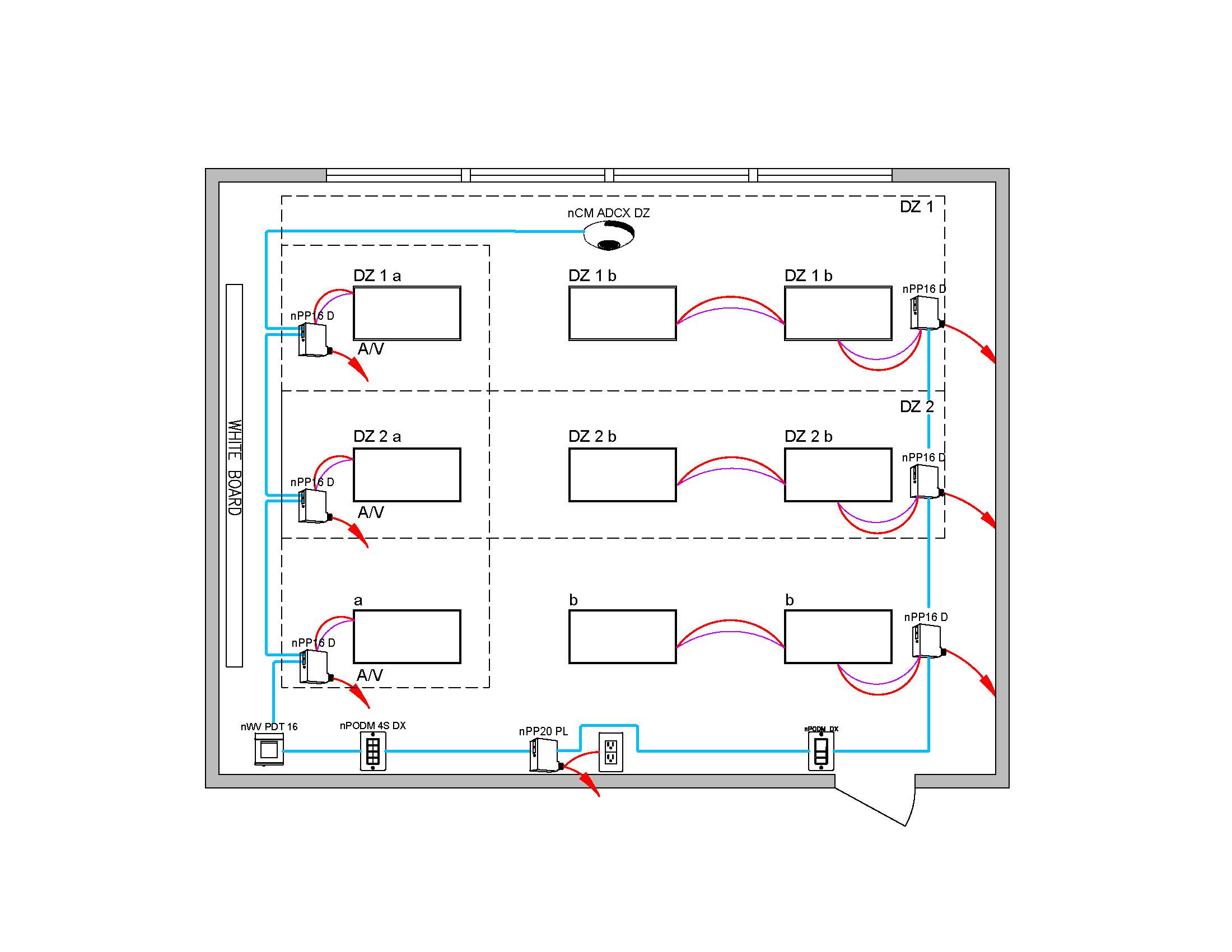
Connect the low voltage. Plan all component locations carefully.

Best Watt Stopper Power Pack Wiring Diagram Wattstopper How To A Bz
Red wire 24vdc from power pack to the 24v terminal on the sensor.
Low voltage occupancy sensor wiring diagram.
Occupancy sensor red 24vdc at 150ma black common blue control red black blue red red black white.
One switchpack one sensor d model dual technology ceiling low voltage occupancy sensor i alla i i c i read all instructions on both sides of this sheet first.
The oac dt ceiling mount low voltage occupancy sensor is a passive infrared pir and ultrasonic us motion sensing lighting control used for energy savings and convenience.
For indoor use only.
Low voltage switch stations.
When the lighting level drops below the set point level the sensor will turn the lights on.
During occupancy the sensor will turn lighting off sixty 60 seconds after reaching or exceeding the set point level.
Detection of walking motion from 8 to 20 ft 274 to 549 m mounting heights.
About press releases sales agent lookup us.
Black wire return from power pack to common terminal on the sensor.
The sfr 7 utilizes passive infrared pir technology to provide 360186.
Low voltage sensors devices requires 33 ma low voltage sensors devices requires 33 ma.
Pir is used to turn the lights on and then either technology is used to keep the lights on.
Install in accordance with all local codes.
Refer to the wiring diagram on the next page for the following procedures.
Sfr 7 the sfr 7 series mini low bay sensor is a compact line voltage occupancy sensor that snaps directly into a small cavity in a fixture.
When motion is detected the blue wire is electronically connected.
Wiring a single lighting load controlled by occupancyconnect.
Do not attempt to power more than 4 devices.
Switchpod manual auto on low volt push button by sensor switch.
The push button switchpod series of low voltage wall stations interface with standard sensor switch occupancy sensors and power packs in order to implement a wide range of single and bi level switching applications.
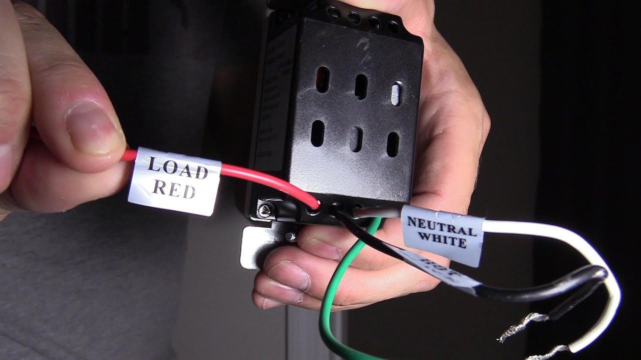
The lighting is controlled by the standard 15 vdc sp20 mv switchpack relay.
Oss24 24vdc requires power pack.
For use with ge switchpacks and systems.
The os is powered by the 24vdc sp r 20 120 receptacle switchpack ps 24v.
Di 000 oss24 05a installation instructions english low voltage wall switch occupancy sensor cat.
Wiring diagram drawing description.
Instruction sheets specification sheets wiring diagrams.
Wiring schematics sensors.
Heavy duty universal voltage power packs.
The los c series ceiling mount occupancy sensors offer a wide range of technologies and can either integrate into lutron systems no power pack needed or function as a stand alone control using a lutron power pack.
Wallbox dimming using only low voltage wiring to the switchbox using occupancy sensor for lighting and control.
High bay occupancy sensors and controllers high bay occupancy sensor.

25 Landscape Lighting Low Voltage Wire Diagram Pictures And Ideas
Typicals Tools And Documents Acuity Brands

Dimming Ballast Wiring Diagram Dimmable Lutron Ecosystem Step Dimmer
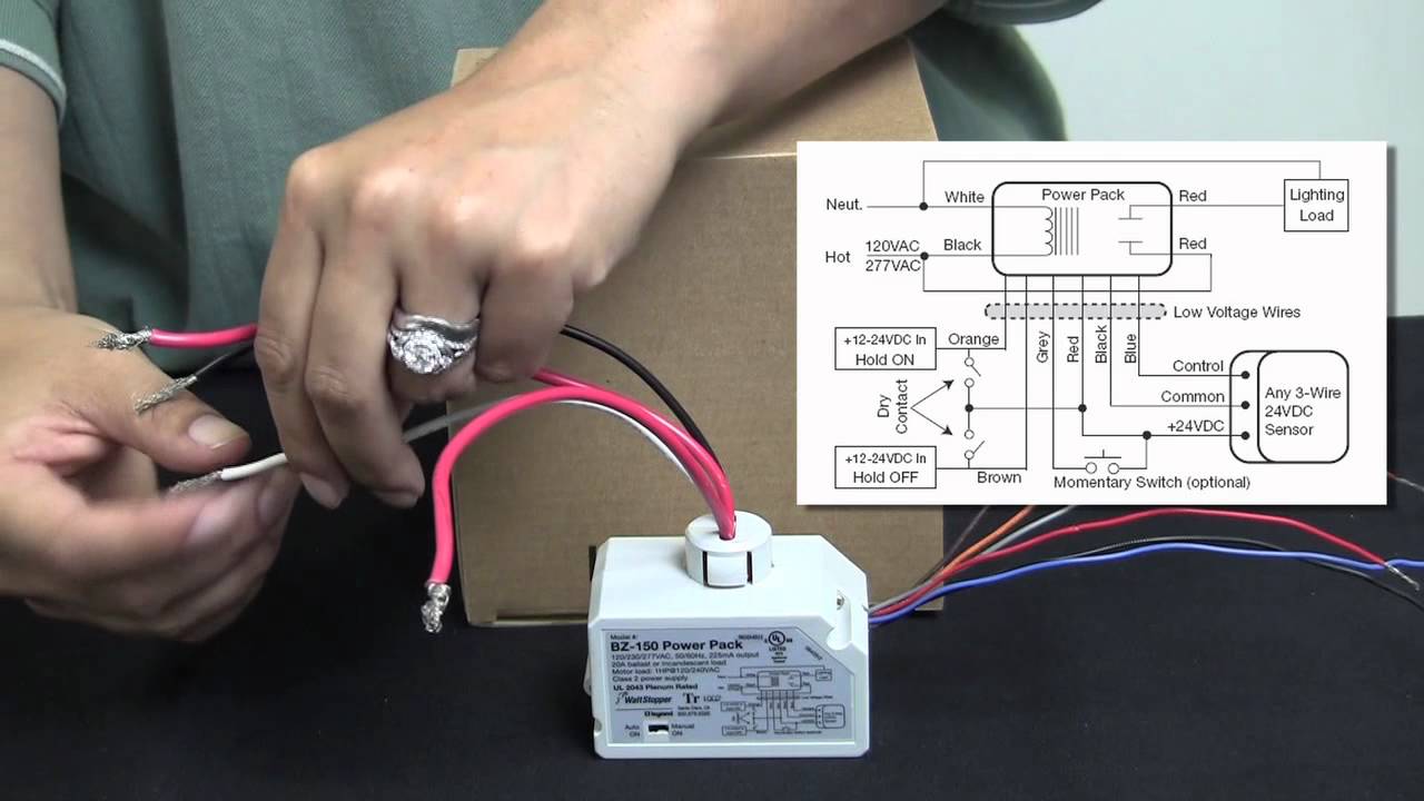
Wattstopper How To Wiring A Bz 150 Universal Voltage Power Pack
Wall Switch Occupancy Sensor Model 1308 Wall Switch Pir Vacancy

Wiring Diagram Likewise Lutron Dimmer Switch Wiring Diagram On

Wiring Diagrams And Schemes Wiring Diagrams From Simpliest To

Kubota Zg23 Wiring Diagram Inspirational Kubota Zg23 Parts

Leviton Occupancy Sensor Wiring Diagram Vacancy Ceiling Switch Loop

0 10v Dimming Ballast Wiring Diagram Diagram Data Schema
Room Controller

Bz 150 Universal Voltage Power Pack Legrand
Easy Way To Wire A Motion Light Switch Installation Youtube
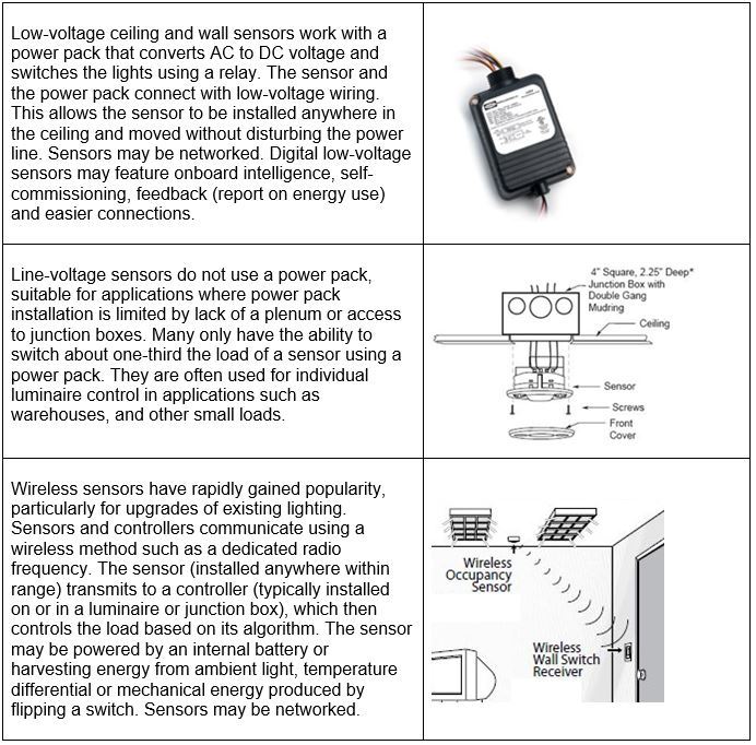
Light Guide Occupancy And Vacancy Sensors
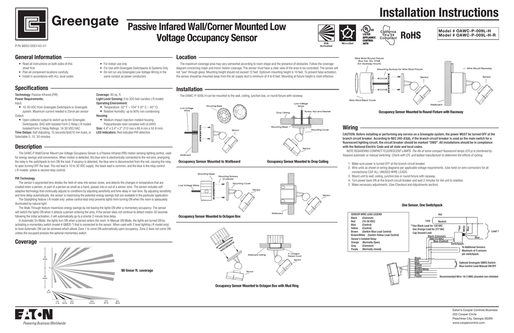
Installation Instructions Passive Infared Wall Corner Mounted Low