6 mike holts illustrated guide to understanding basic motor controls unit 1 basic principles of motor controls different manufacturers of control devices as well as books about motor controls use different methods of showing the control circuit wiring. For push button control stations start stop control wiring diagrams 4 single station maintained contact push buttons.

Control Wiring 3 Wire Control Start Stop Circuit
It is your job to improvise a.
Wiring diagram start stop motor control.
Pressing start immediately sends power through the start pushbutton and the seal in contacting energizing the coil.
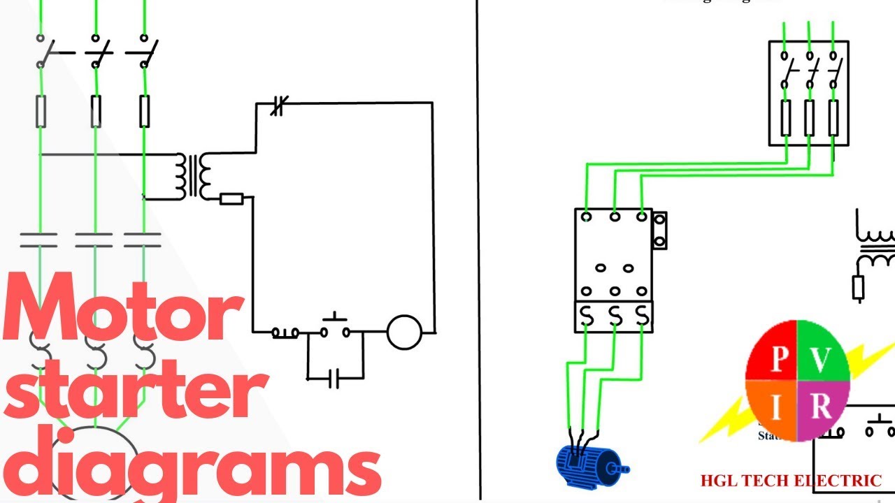
Motor starter schematic and wiring diagram.
Ladder diagram basics 4 multiple stop start stations.
With the switch closed the control circuit acts as a normal stopstart station controlling a load connected to the pilot device power is sitting on the start and seal in terminals of the pushbutton.
Wiring diagram book a1 15 b1 b2 16 18 b3 a2 b1 b3 15 supply voltage 16 18.
Motor start stop circuits are very common in industry and apply to applications beyond electric motors.
Whenever we need to start and stop the motor from more than one point then we may expand it through push buttons in the motor control circuit for example you may use this alternative power control wiring diagram of controlling a three phase motor from mo re than two places.
Ac motor control circuits ac electric circuits.
This is a realistic scenario where the only type of switch you have available is a spdt but the wiring diagram calls for something different.
Optional x1 x2115 v 230 v h1 h3 h2 h4 optional connection electrostatically shielded transformer f u 6 off on m l1 l2 1 2 stop ol m start 3 start start fiber optic transceiver class 9005 type ft fiber optic push button.
This video explains the basics of a simple start stop motor control circuit.
Start stop 3 wire control.
The motor starts automatically.
The start contacts are unaffected.
The most common use of 3 wire control is a startstop control.
Basic startstop circuit.
For example in figure 13b1 the control wiring from the start stop.
Starting a three phase motor.
The control station wiring diagram is a representation of the physical station showing the relative positions of.
Motor 3ct to 120 v separate control ot is.
See image below for an example of 3 wire control being used to pull in a contactor to start a 3 phase motor.

Motor Control Fundamentals Wiki Odesie By Tech Transfer

How To Read Washing Machine Wiring Diagram Wiring Diagram
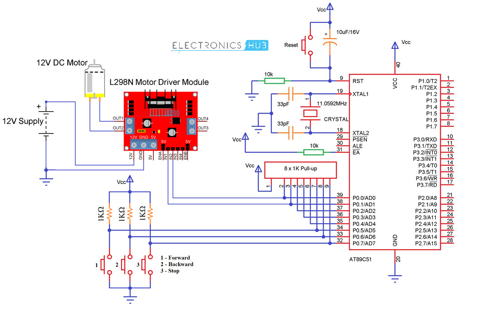
Interfacing Dc Motor With 8051 Microcontroller Using L293d

Photo Control Wiring Diagram Wiring Diagram Database
Basic Wiring For Motor Control Technical Data Guide Eep

Basic Motor Starter Ladder Diagram Circuit Diagram Basic Circuit

Motor Sd Control Circuit Diagram Motor Repalcement Parts And Diagram

Ac Motor Control Circuits Ac Electric Circuits Worksheets

Ac Motor Control Circuits Ac Electric Circuits Worksheets
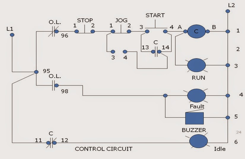
Jog Motor Control Motor Control Operation And Circuits
Lessons In Electric Circuits Volume Iv Digital Chapter 6

Push On Start Wiring Diagram Online Wiring Diagram
3 Wire Start Stop Diagram Basic Electronics Wiring Diagram

555 Timer Stepper Motor Controller Circuit

Control Wiring 3 Wire Control Start Stop Circuit