My site is dedicated to helping you get connected. Replacing electrical outlet repair electrical outlets.

Wiring Diagram Moreover Nest Thermostat Wiring Diagram On Wiring
Hiring an electrician is usually the best way to go where 120 volt circuits are concerned but if you are up to it you might save money by doing some basic electrical work yourself.
Basic electrical outlet wiring diagram.
Wiring examples and instructions with video and tutorials.
Whether its trying to figure out that rats nest behind your television set or just simply changing over an electrical wall switch or outlet im here to help.
How to wire a simple 120v electrical circuit.
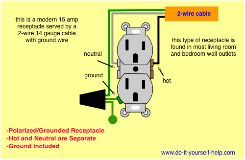
The slots are different sizes to accept polarized plugs but it lacks a grounding slot.
It shows how the electrical wires are interconnected and can also show.
A basic explanation of the wiring of an electrical receptacle plug in so youll know what to do when replacing one.
A wiring diagram is a simple visual representation of the physical connections and physical layout of an electrical system or circuit.
Wiring an ungrounded polarized outlet.
General materials and wiring techniques for residential wiring sam maltese shows some general information regarding house wiring.
Usually the wiring which you are installing will be affixed to the final outlet in the current run of.
Electrical wiring in the us follows the same basic color codes.
Learn how to wire outlets test gfci circuits and troubleshoot dead outlets with tips to work safely.
This is how to rough in electrical wiring yourself.
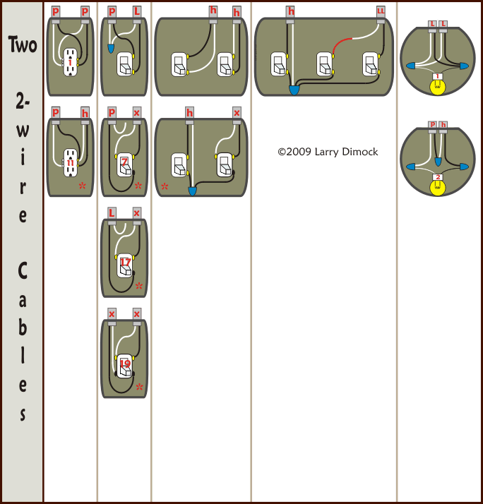
In the diagram below a 2 wire nm cable supplies line voltage from the electrical panel to the first receptacle outlet boxthe black wire line and white neutral connect to the receptacle terminals and another 2 wire nm that travels to the next receptacle.
With smartdraw you can create more than 70 different types of diagrams charts and visuals.
And second its easier to press the outlet back into the box if fewer of its screws are connected to wires.
This outlet does not make use of a ground wire and there is no protection against electrocution as provide by the grounded receptacle.
Use this easy method to install a new electrical outlet without a lot of wire pulling.
This is an older version of the receptacle outlet in the first diagram.
Electrical wiring outlets.
Connect to the outlet.
Instead use wire connectors to connect the neutral hot and ground wires along with 6 in long pigtails then connect the pigtails to the outlet.
Red and black wires denote live wires white wires serve as the ground and blue yellow or other colors are used for switches or other specific purposes.
Add an electrical outlet.

Electrical Outlet Wiring Diagram Series Versus Parallel Electrical

Wiring Diagram For A 30 Amp 240 Volt Circuit Breaker Electrical

Range Plug Wiring Wiring Diagram

Wiring As Well Square D Pressure Switch On Square D Drum Switch
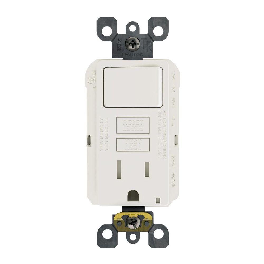
Gfci Combo Switch Electrical Outlets Receptacles Wiring

Wiring Diagram For Gfci Schematic Online Wiring Diagram
Home Electrical Switch Wiring Diagram Basic Electronics Wiring Diagram

Box Diagram Gfci Switch Outlet Bo Diagram Electrical Wire Colors

Epic Guide To Diy Van Build Electrical How To Install A Campervan

Light Socket Wiring Diagram Australia Online Wiring Diagram

Electric Light Switch Wiring Diagram Basic Electronics Wiring Diagram

Socket To Switch Wiring Diagrams Online Wiring Diagram
Wiring Diagrams For Electrical Receptacle Outlets Do It Yourself
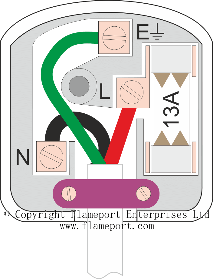
Electrical Plug Wiring Colours Diagram Data Schema

Colors For Wiring House Receptacles Wiring Diagram Data Schema